

Auxiliary device of dust collector
An accessory device and dust collector technology, applied in the direction of the suction nozzle, etc., can solve the problems of time-consuming disassembly and assembly of the connecting pipe, dust removal from the upper part of the high position, etc.
- Summary
- Abstract
- Description
- Claims
- Application Information
AI Technical Summary
Problems solved by technology
Method used
Image

Examples
Embodiment Construction
[0059] Hereinafter, embodiments of the present invention will be described in detail with reference to the drawings.
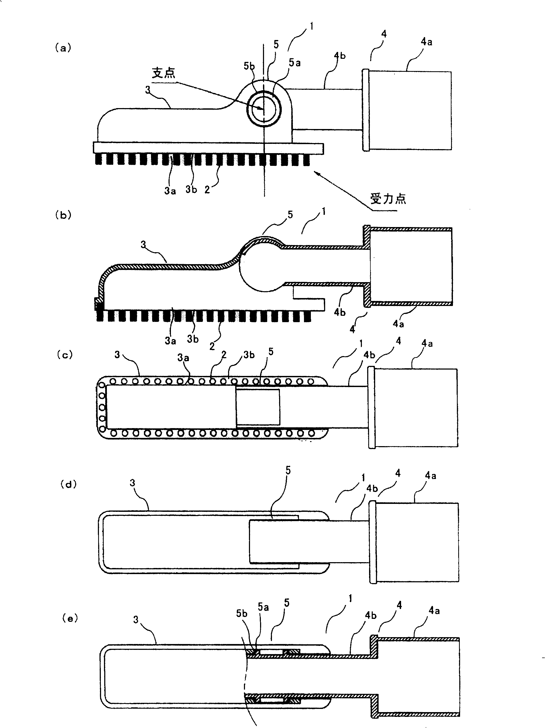
[0060] figure 1 It is a figure which shows the structure of one embodiment of the attachment for dust collectors of this invention, (a) is a side view, (b) is a side sectional view, (c) is a bottom view, (d) is a top view, (e) is A sectional view of main parts viewed from the top side.
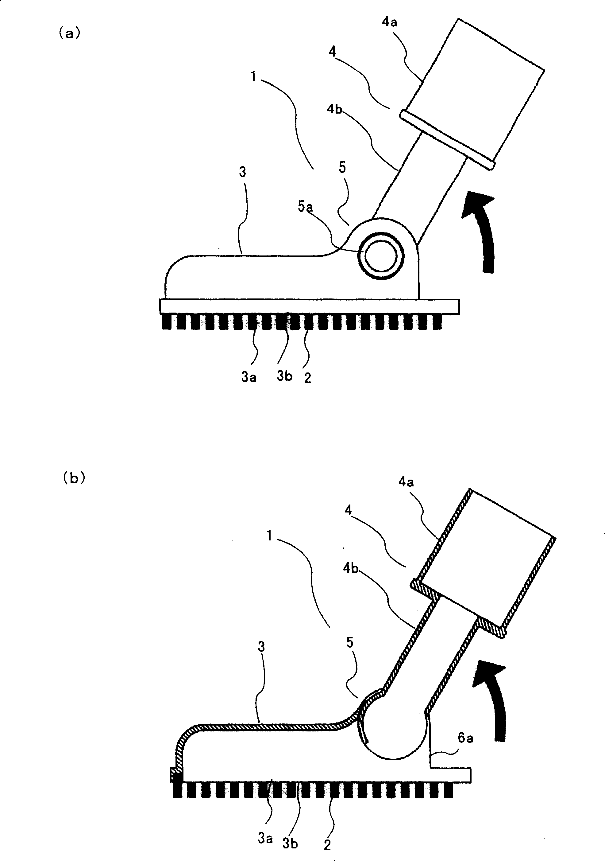
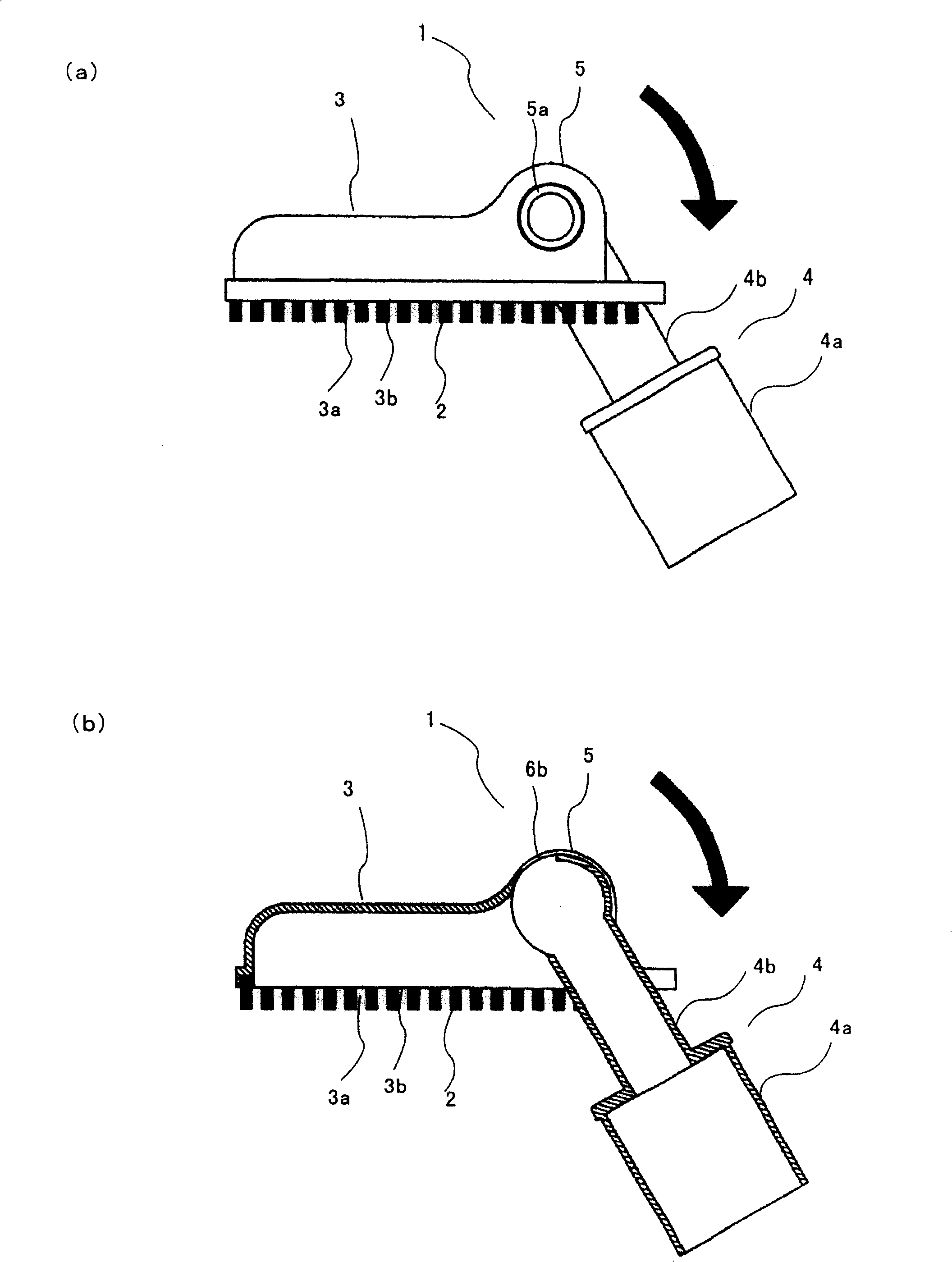
[0061] The dust collector attachment 1 of the present embodiment is provided with: an elongated suction port 3 having a suction port 3a with a brush 2 bristled at the edge of the opening; On the connected hose or extension pipe; the connecting part 5, which makes the connecting pipe 4 communicate with the suction port 3, and connects the connecting pipe 4 as figure 2 As shown, it can be rotated to the direction of the back side of the suction port 3a and as shown image 3 As shown, it is rotatably coupled in a direction to rotate to the side of the suction port 3a.
[006...
PUM
 Abstract
Description
Claims
Application Information