
Electromagnetic mixing roller of two cool areas of highfield unburnt earthenware

A technology of electromagnetic stirring and secondary cooling zone, applied in the field of electromagnetic stirring rollers, can solve the problems of small iron core magnetic conduction area, large iron core teeth, small ampere turns and magnetic conduction area, etc., to increase the electromagnetic stirring force, Increase the electromagnetic stirring force and improve the effect of space utilization

Active Publication Date: 2009-01-14
HUNAN ZHONGKE ELECTRIC
View PDF6 Cites 0 Cited by
  • Summary
  • Abstract
  • Description
  • Claims
  • Application Information

AI Technical Summary

Problems solved by technology

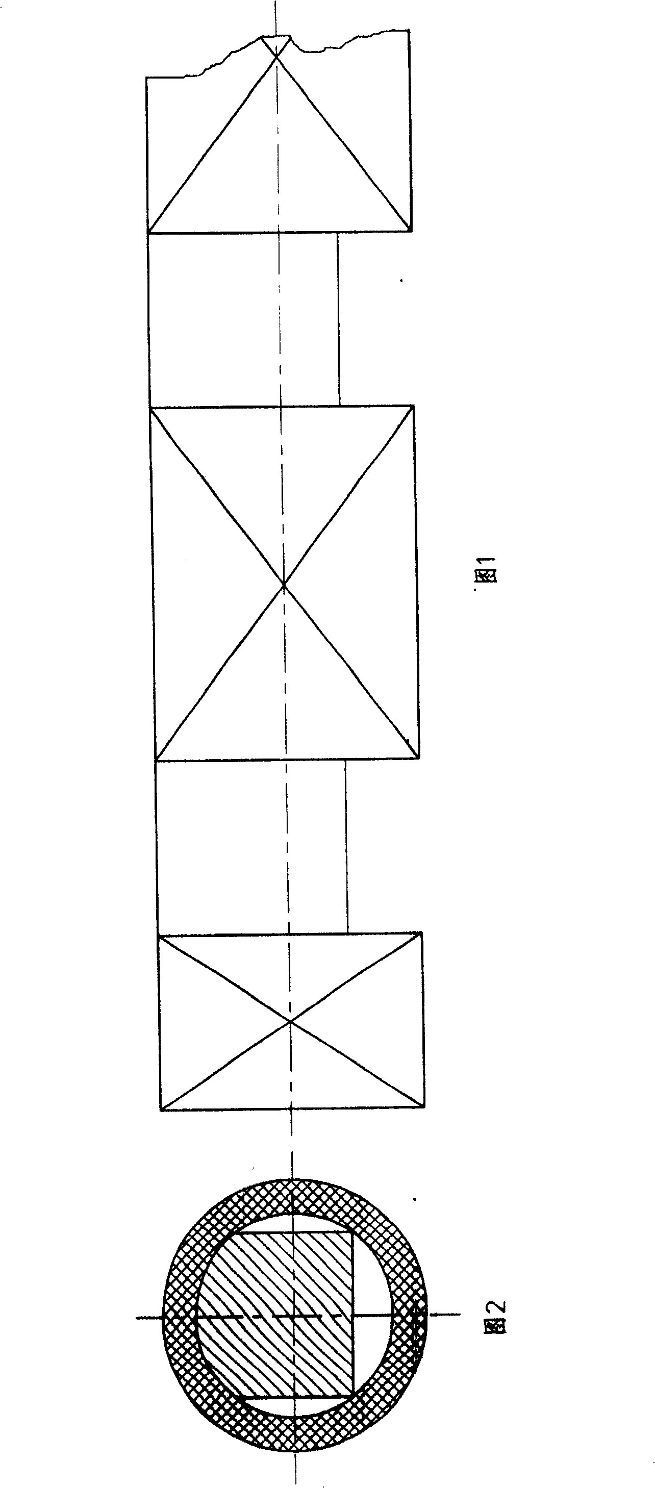
The electromagnetic roller with this structure has the following disadvantages: a. The iron core teeth occupy a relatively large volume, which reduces the proportion of the winding and iron core cross-section, and the ampere-turns and magnetic permeability area are small, so the magnetic field is also small
The defects of E-shaped slotted iron core and Kramm circular winding have small magnetic area, large magnetic resistance and large magnetic flux leakage, which have seriously affected the use effect of the electromagnetic stirring roller.

Method used


Image

  • Electromagnetic mixing roller of two cool areas of highfield unburnt earthenware
  • Electromagnetic mixing roller of two cool areas of highfield unburnt earthenware
  • Electromagnetic mixing roller of two cool areas of highfield unburnt earthenware

Examples


Embodiment Construction

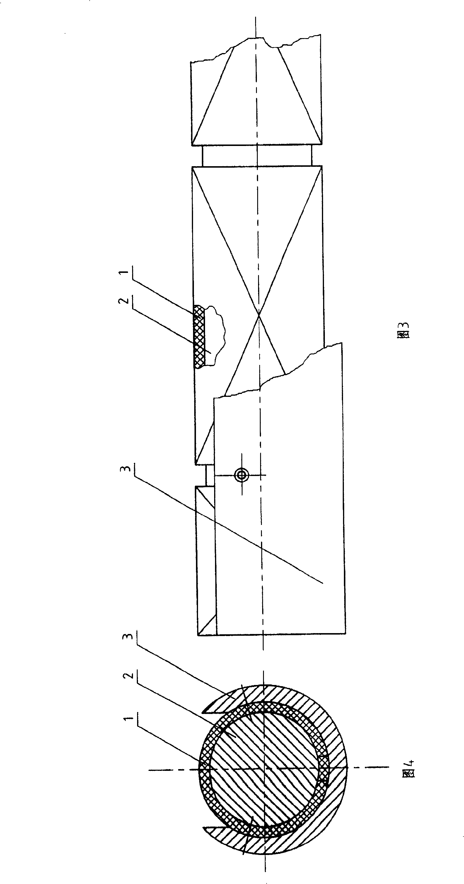
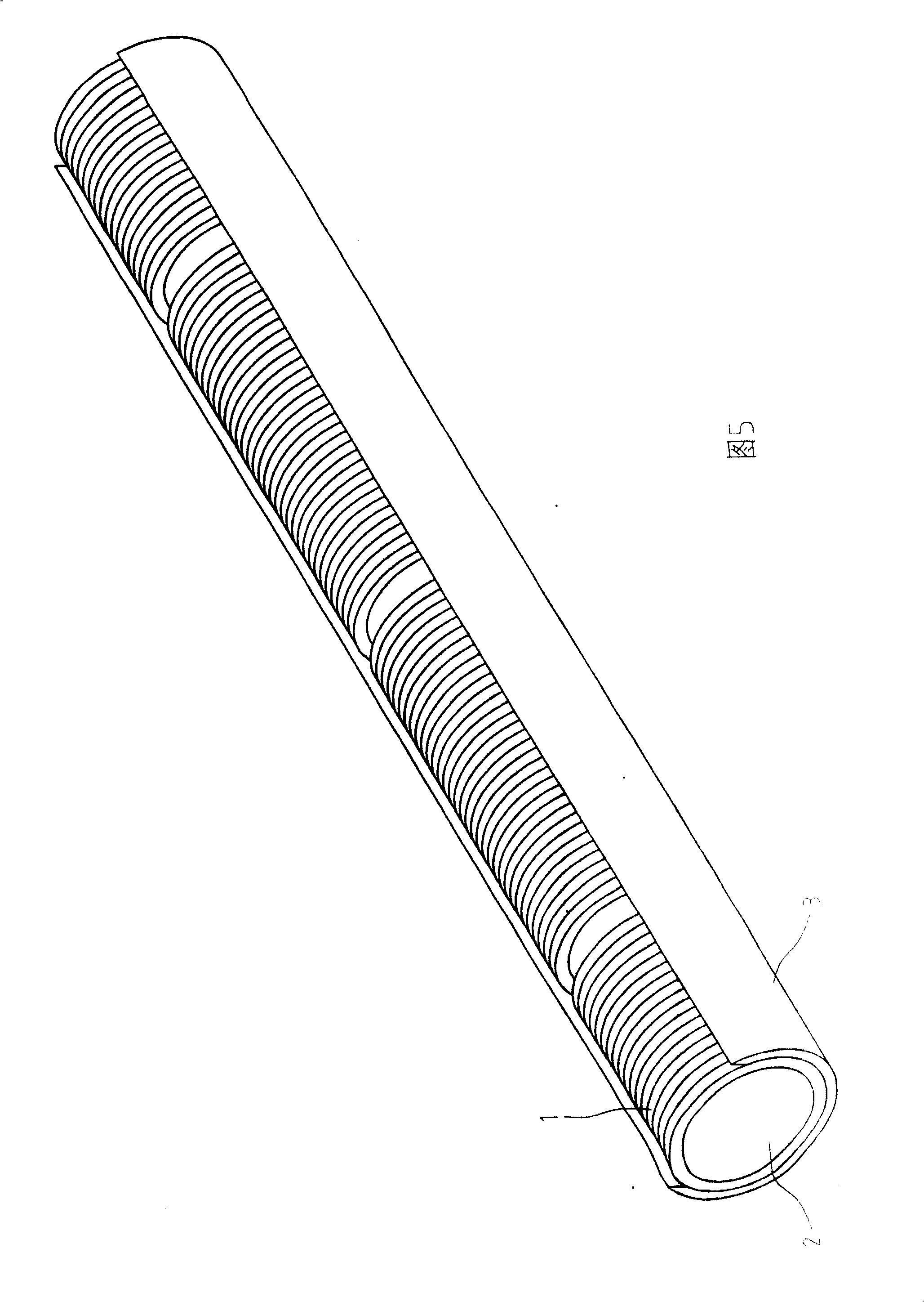
[0012] As can be seen from Figures 3 and 4, the present invention includes a winding (1) and an iron core (2), which is characterized in that the iron core (2) adopts a cylindrical iron core (2) without tooth grooves, and the stirring roller is provided with a magnetic shielding ring (3), the outer surface of the magnetic shielding ring (3) is a non-working surface, and the surface not covered by the magnetic shielding ring (3) is a working surface.

[0013] The winding (1) in the present invention is wound at intervals or continuously on the periphery of the cylindrical iron core (2). The magnetic shielding ring (3) is sleeved on the outer layer of the winding (1) and the cylindrical iron core (2). The magnetic shielding ring (3) has an opening where the winding (1) is exposed as the working surface of the stirring roller. The iron core (2) is cylindrical without teeth and slots.

[0014] The inventor of the present invention trial-produced a prototype with the same size as...


PUM


Abstract

The present invention relates to electromagnetic stirring roller for continuous metal casting, and is especially one kind of high magnetic field two cold plate blank electromagnetic stirring roller. The electromagnetic stirring roller includes a winding and a cylindrical iron core, and has shielding rings to mask the non-working surface. Adopting cylindrical iron core without teeth and slots results in high space utilization rate of the winding, increased magnetic conducting area of the iron core, raised magnetic field strength and enhanced electromagnetic stirring force. Shielding the non-working surface with shielding rings can minimize the magnetic leakage, increase the magnetic field strength in the working surface and enhance the electromagnetic stirring force.

Description

technical field [0001] The invention relates to an electromagnetic stirring roller used in the metal continuous casting process, in particular to an electromagnetic stirring roller in a high magnetic field slab secondary cooling zone. Background technique [0002] The electromagnetic stirring in the secondary cooling zone of the slab usually adopts the following three forms: a. Roller traveling wave magnetic field type, b. Roller type traveling wave magnetic field type, c. Magnetic pole insertion type traveling wave magnetic field type. The latter two are most used now. Among them, the roller-type traveling wave magnetic field type directly places the electromagnetic inductor in the support roller to form an electromagnetic stirring roller, and its shape is the same as that of a common roller. It can be easily installed on the slab continuous casting machine without changing the structure of the continuous casting machine, so it is easily accepted by users. However, due to...

Claims


Application Information

Patent Timeline
Patent Type & Authority Patents(China)
IPC IPC(8): B22D11/115
Inventor 董元龙叶劲松胡长义魏建国郭炜李融李爱武
Owner HUNAN ZHONGKE ELECTRIC
Learn More