Rear-projection screen, optical element and manufacturing method thereof

A technology of optical components and manufacturing methods, applied to the optical components of rear projection screens and its manufacture, and in the field of rear projection screens, can solve the problems of brightness reduction, limitation of contrast and resolution, thickness tolerance, etc., and achieve increased area, contrast and The effect of improving the resolution and increasing the yield rate

Inactive Publication Date: 2009-01-14
PRODISC TECH INC
View PDF4 Cites 0 Cited by
  • Summary
  • Abstract
  • Description
  • Claims
  • Application Information

AI Technical Summary

Problems solved by technology

However, when the incident light 1000 passes through the first surface 110 and is scattered on the second surface 111 after being focused (focus point P), the outgoing light 1001 will be blocked by the light absorbing layer 120, resulting in a decrease in brightness. 120 has certain width and height restrictions
It is worth mentioning that the above-mentioned phenomenon will be more serious due to the thickness tolerance in the production of the lenticular lens (that is, the focal point P moves forward or backward due to the thickness tolerance in the production), which will lead to light absorption The width of the layer is further reduced
[0004] In addition, as shown in FIG. 1C, due to the limitation of the width of the light absorbing layer 120, the ambient interference light 1002 may penetrate the area where the light absorbing layer 120 is not formed, and further, there will be multiple reflected light 1003 from the The area where the light absorbing layer 120 is formed penetrates out, this phenomenon will limit the improvement of contrast and resolution
[0005] In addition, in the manufacturing method of the rear projection screen 1 in the prior art, since the light absorbing layer 120 is formed on each strip-shaped convex portion 111b of the lenticular lens 11, the surface flatness of each strip-shaped convex portion 111b and the printing time The pressure control is an important parameter of the manufacturing process, so it also leads to another bottleneck in the process yield improvement of the light absorbing layer 120 during printing.

Method used


Image

  • Rear-projection screen, optical element and manufacturing method thereof
  • Rear-projection screen, optical element and manufacturing method thereof
  • Rear-projection screen, optical element and manufacturing method thereof

Examples


Embodiment Construction

[0061] The rear projection screen according to a preferred embodiment of the present invention will be described below with reference to related drawings, wherein the same components will be described with the same symbols.

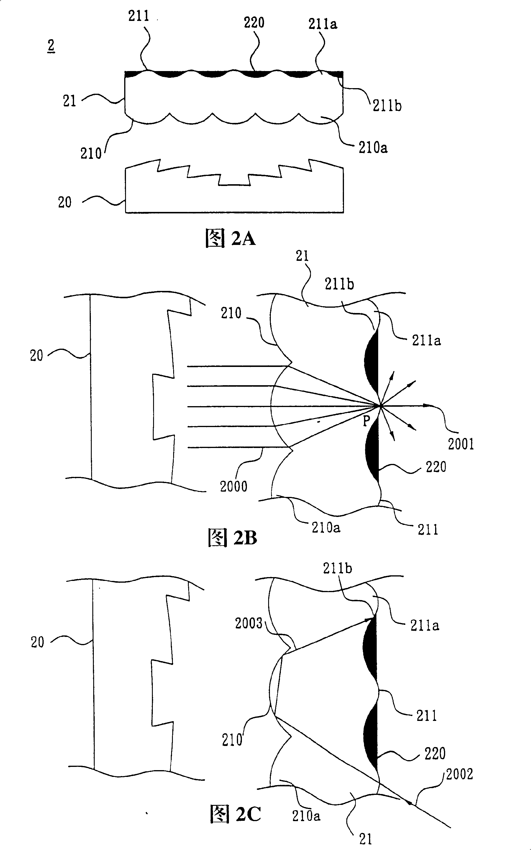
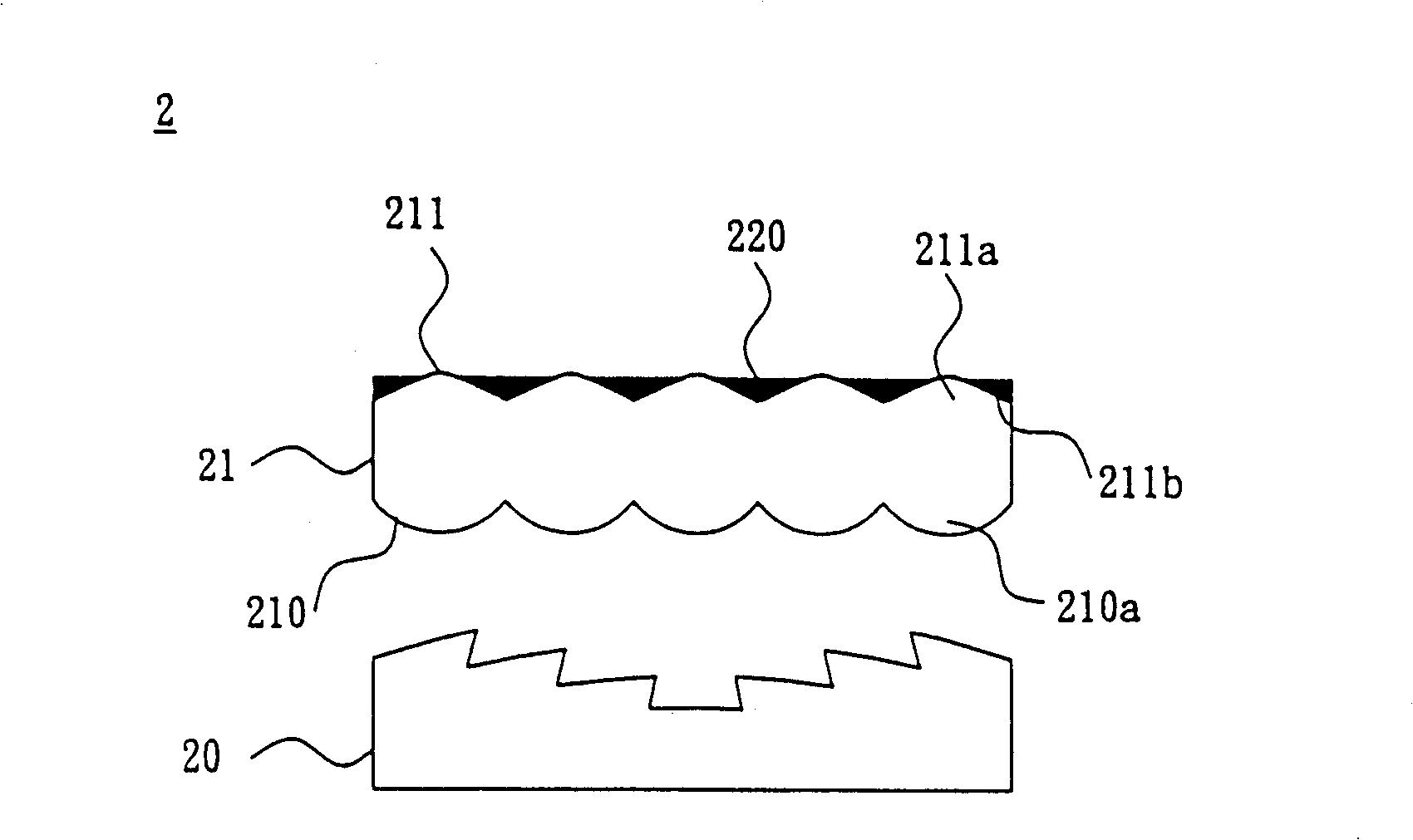
[0062]Please refer to Figures 2A, 2B and 2C (Figures 2B and 2C are partial enlarged views of Figure 2A), the rear projection screen 2 according to a preferred embodiment of the present invention includes a first optical element 20 and a second optical element 21 .

[0063] The first optical element 20 is used to collect light, so that originally divergent light can be collected and entered into the viewer's sight. In this embodiment, the first optical element 20 is a Fresnel lens. In this way, the light rays can be collected and exit the Fresnel lens in a parallel manner.

[0064] The second optical element 21 has a first surface 210 and an opposite second surface 211, the first surface 210 is adjacent to the first optical element 20, and the first surfa...


PUM


Abstract

A rear projection screen comprises the first optical element and the second optical element. The two are adjacent-set as the second optical element has the first surface and the second surface opposite to the first. Both surfaces have multiple columnar snug separately, a dent is formed at interval place of each column snug on the second surface, each dent is opposite to the columnar snug of the first surface and is formed at opposite position between the columnar snugs. Each dent is filled with a light absorption material. An optical element and its manufacturing method are also provided by the present invention.

Description

technical field [0001] The invention relates to a screen, an optical element of the screen and a manufacturing method thereof, in particular to a rear projection screen, an optical element of the rear projection screen and a manufacturing method thereof. Background technique [0002] With the popularization of HDTV and DVD Player, the image quality of large-size displays has been paid more and more attention by the market. Among large-size displays, projection display devices have always received great attention because of their application occasions and price considerations, especially rear projection TVs. In the rear projection TV, the main function of the rear projection screen is to project the image in the projector. It is characterized by large size, high image quality and thinness in the market. Therefore, the key points to be considered in the design of the rear projection screen include: Observing the brightness of the angle, increasing the image contrast and resol...

Claims


Application Information

Patent Timeline
Patent Type & Authority Patents(China)
IPC IPC(8): G03B21/60G02B1/10G03B21/625H04N9/31
Inventor 张仁怀王志鸿刘江兴
Owner PRODISC TECH INC
Why Eureka
Try Eureka