
Hydrodynamic clutch

A hydraulic coupling, primary technology, applied in clutches, hydraulic resistance brakes, clutches, etc., can solve problems such as failures and expensive slip ring sealing devices, and achieve the effect of simple sealing

Inactive Publication Date: 2009-01-21
VOITH TURBO GMBH & CO KG
View PDF9 Cites 0 Cited by
  • Summary
  • Abstract
  • Description
  • Claims
  • Application Information

AI Technical Summary

Problems solved by technology

The counter seal is therefore conventionally implemented in the form of an expensive slide ring seal
This slip ring seal is expensive and prone to failure

Method used


Image

  • Hydrodynamic clutch
  • Hydrodynamic clutch
  • Hydrodynamic clutch

Examples


Embodiment Construction

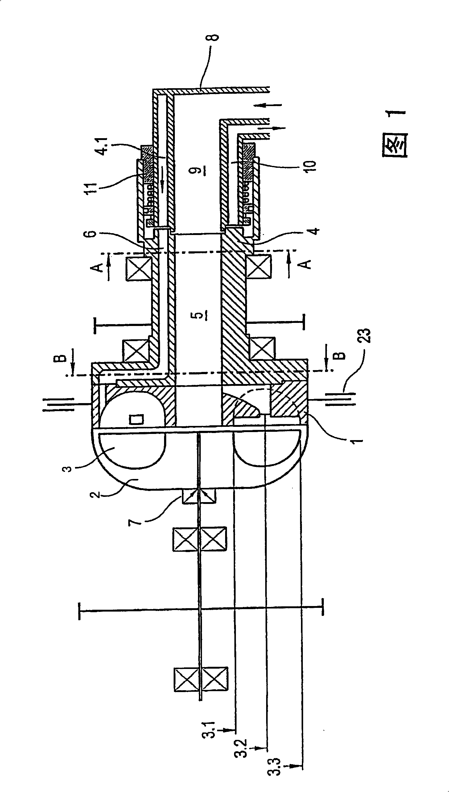
[0028] In the axial section shown in FIG. 1 , the primary wheel 1 is seen, which is arranged on the drive shaft 4 . In detail, the primary wheel 1 is screwed onto the drive shaft 4 at the end face and is sealed such that the end face contour of the drive shaft 4 forms part of the end section of the feed channel 5 in the area of ​​the circumference 3.2 Zhongtong to the center of Studio 3. In addition, the feed channel 5 extends in the longitudinal direction on the longitudinal axis of the drive shaft 4 and is formed here as a through-opening. This has the advantage that through the axial section of the input channel 5 the screws shown, with which the secondary wheel is coupled at the end to the shaft 7, can be tightened or loosened.

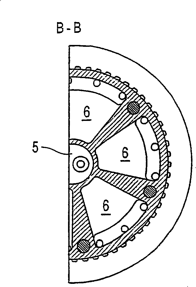
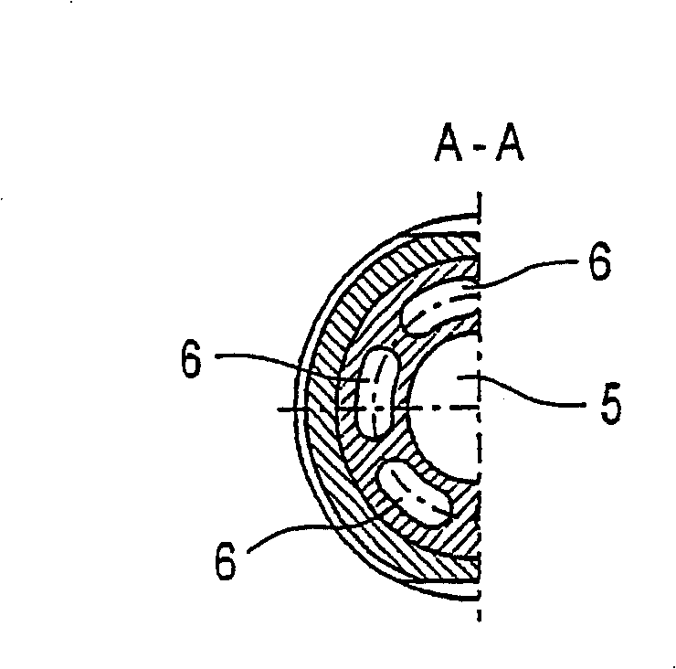
[0029] Radially outside the inlet channel 5 , a plurality of outlet channels 6 are formed in the drive shaft 4 for discharging the working medium from the working chamber 3 of the hydrodynamic coupling. A cross-section of such an outlet channel ...


PUM


Abstract

The invention relates to a hydraulic coupling, which has a primary wheel and a secondary wheel, the primary wheel and the secondary wheel jointly form a torus-shaped working chamber, the primary wheel is arranged on a drive shaft Or integrally formed with the drive shaft, wherein at least one inlet channel for feeding the working medium into the working chamber and at least one outlet channel for simultaneously discharging the working medium from the working chamber are formed in the drive shaft.

Description

technical field [0001] The invention relates to a hydraulic coupling, in particular to a pipeline arrangement for a working medium inside the hydraulic coupling. Background technique [0002] Fluid couplings are disclosed. A special field of application is that of turbocompound systems, in which an exhaust gas turbine is arranged in the powertrain in the exhaust gas flow of the internal combustion engine and is in drive connection with the crankshaft. In such a system, a hydrodynamic coupling for transmitting power or torque is advantageously connected in the drive connection between the exhaust gas turbine and the crankshaft. When the primary wheel of such a hydrodynamic coupling is driven by the exhaust gas turbine, the primary wheel drives the secondary wheel of the hydrodynamic coupling through the working medium circulation in the working chamber of the hydrodynamic coupling, which is usually passed through a suitable The transmission is connected to the crankshaft. ...

Claims


Application Information

Patent Timeline
Patent Type & Authority Patents(China)
IPC IPC(8): F16H41/30F16D33/06
CPCF16D57/04F16D33/06F16D33/00
Inventor 马库斯·克莱
Owner VOITH TURBO GMBH & CO KG
Learn More