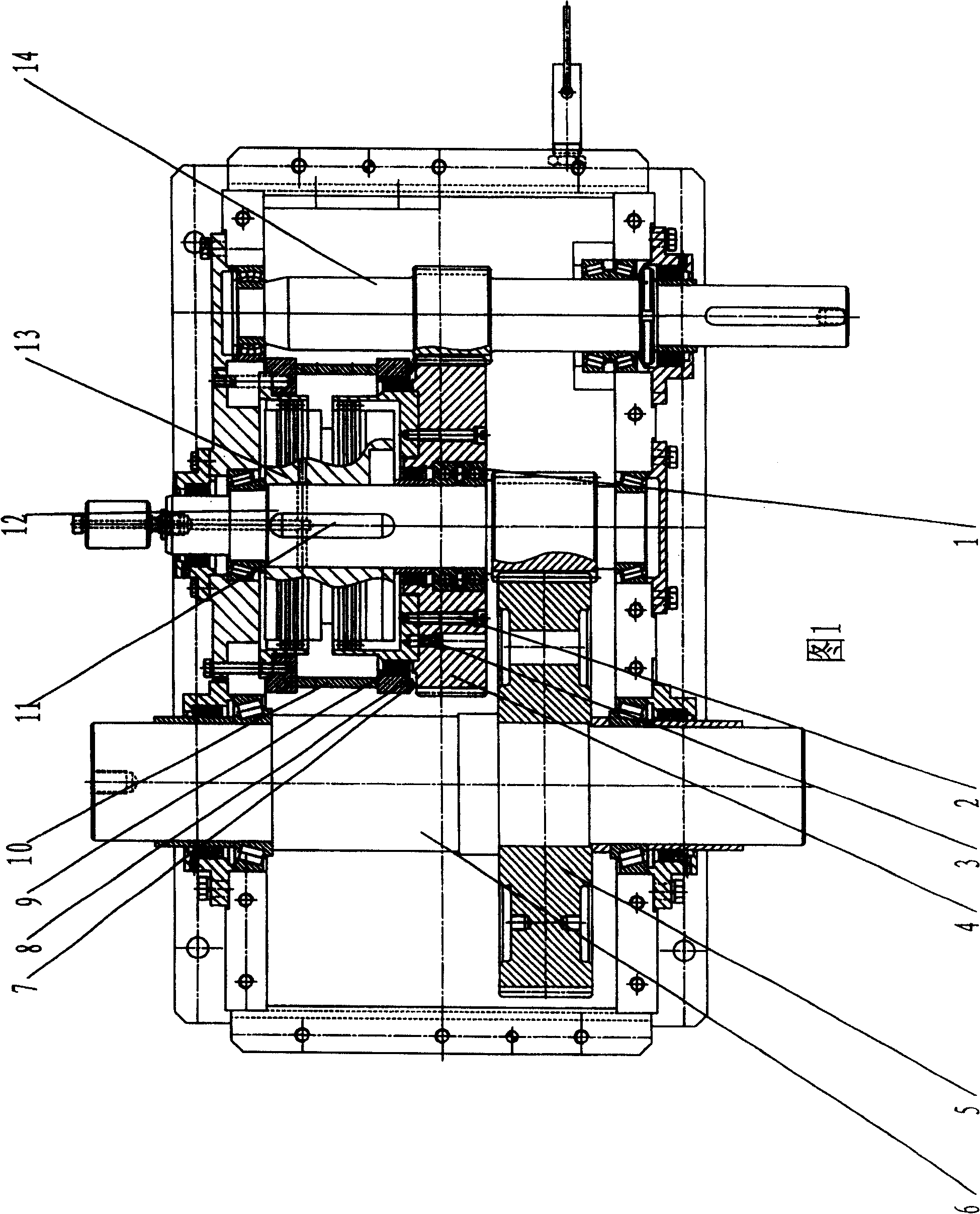
Dynamic intermittent running speed reducer
A speed reducer, dynamic technology, applied in the direction of mechanical equipment, transmission devices, gear transmission devices, etc., can solve the problems of adverse effects of power machinery, system complexity, increase of external transmission links, etc., to achieve compact structure, reliable operation, no rigidity impact effect
- Summary
- Abstract
- Description
- Claims
- Application Information
AI Technical Summary
Problems solved by technology
Method used
Image
Examples
Embodiment 1
[0013] Embodiment 1: a dynamic intermittent operation reducer, including a reducer input shaft 14, a first-stage reduction transmission gear 4 and a second-stage reduction transmission gear shaft 12, the first-stage reduction transmission large gear 4 is in phase with the reducer input shaft 14 Mesh, and through the rolling bearing 1 empty sleeve on the second-stage reduction transmission gear shaft 12; between the first-stage reduction transmission large gear 4 and the second-stage reduction transmission gear shaft 12, there is a device that can dynamically control the combination of the two. and disengaged combination clutch / brake 13. The rim end of the combined clutch / brake 13 is fixedly connected to the first-stage reduction transmission large gear 4 through the connecting screw 2 and the positioning pin 3; while the hub end is connected to the second-stage reduction transmission gear shaft 12 through the flat key 11, and the second-stage The reduction transmission bull ge...
Embodiment 2
[0017] Embodiment 2: The friction disk of the hydraulically driven combined clutch / brake 13 in the present invention must work under the "wet" cooling state, and the working fluid is hydraulic oil; the lubricating oil of the gear and the bearing is gear oil, in order to avoid both For mixing, the present invention sets an isolation band on the periphery of the combination clutch / brake 13.
[0018] The advantages of the present invention are as follows: firstly, the structure is compact and the appearance is beautiful; secondly, the input shaft will always be in a rotating state; thirdly, the combination clutch / brake driven by hydraulic pressure is used, which works smoothly and reliably without hard impact; fourthly, it can be realized conveniently Automatic control of intermittent operation; Fifth, a wide range of applications and a broad market prospect.
PUM
 Abstract
Description
Claims
Application Information
 - R&D
- Intellectual Property
- Life Sciences
- Materials
- Tech Scout
- Unparalleled Data Quality
- Higher Quality Content
- 60% Fewer Hallucinations
Browse by: Latest US Patents, China's latest patents, Technical Efficacy Thesaurus, Application Domain, Technology Topic, Popular Technical Reports.
© 2025 PatSnap. All rights reserved.Legal|Privacy policy|Modern Slavery Act Transparency Statement|Sitemap|About US| Contact US: help@patsnap.com

