Position indicating and locking device

A locking device and indicating technology, which is applied to switchgear, switchgear components, pull-out switchgear, etc., can solve the problems of inaccurate, unreliable, and insufficiently high precision of circuit breakers, and achieve accurate and reliable locking structure, ensuring Positioning accuracy, the effect of eliminating visual errors

Active Publication Date: 2009-02-04
JIANGSU DAQO KFINE ELECTRIC
View PDF4 Cites 0 Cited by
  • Summary
  • Abstract
  • Description
  • Claims
  • Application Information

AI Technical Summary

Problems solved by technology

The existing problem is: due to the deviation of the operator's viewing angle and the deviation of the position during the forward and backward movement, the circuit breaker is not in place accurately, which can easily cause misoperation
However, the analysis shows that there are still the following deficiencies: 1. The slide plate has no direct positioning function, and it needs to use the square shaft fixedly connected to it, which is not only complicated in structure, but also not high enough in precision; The realization of the convex structure is not reliable enough; 3. The indicating device is a rotating pointer, which is prone to visual errors

Method used


Image

  • Position indicating and locking device
  • Position indicating and locking device
  • Position indicating and locking device

Examples


Embodiment 1

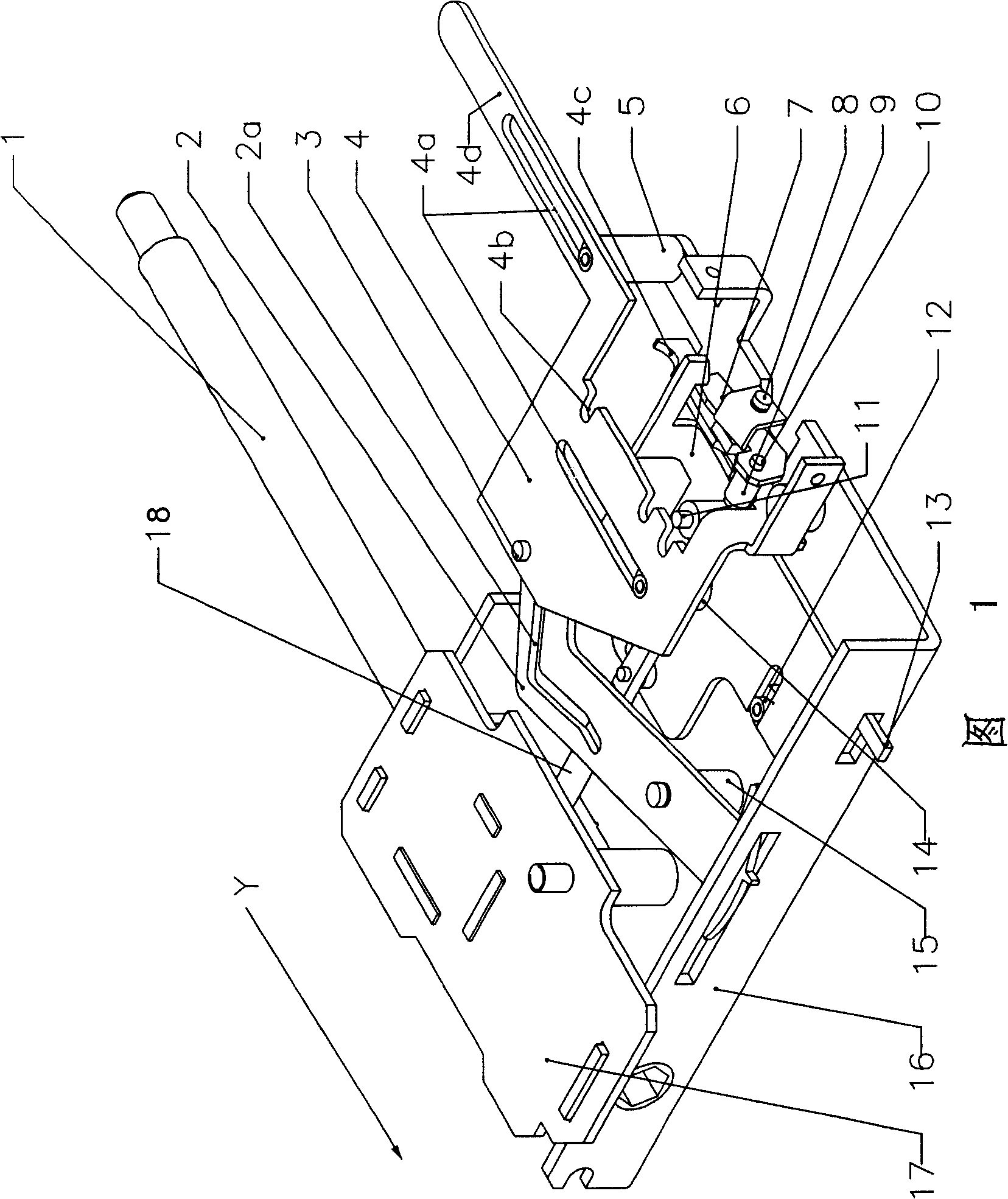
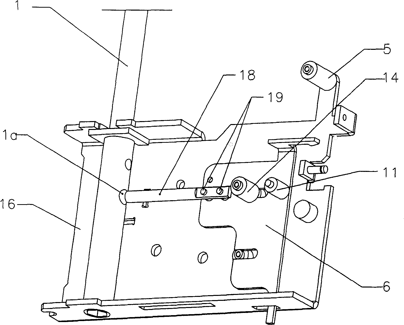
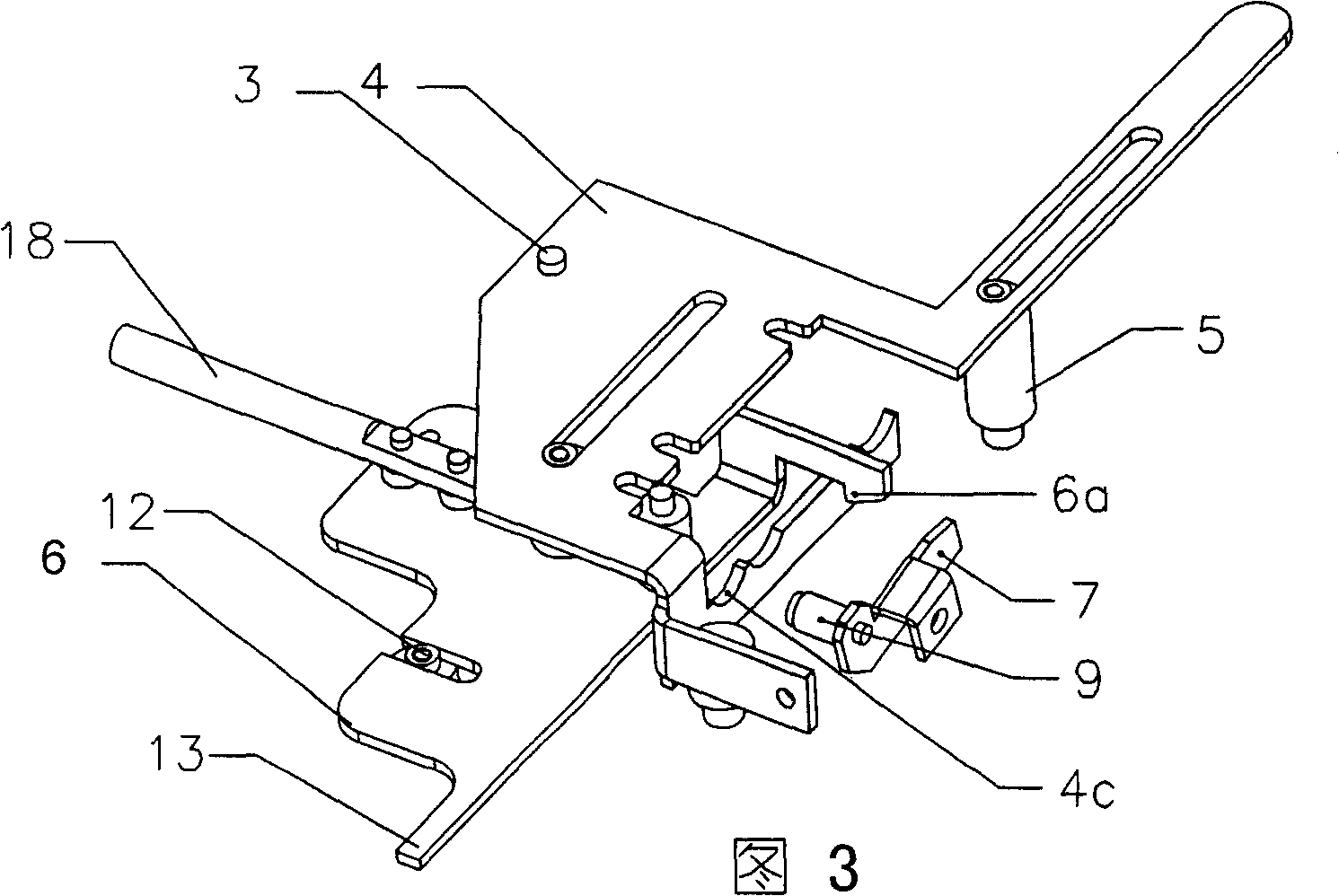
[0017] The position indication and locking device of the drawer type circuit breaker in this embodiment is shown in Figures 1, 2, and 3. It is composed of indicator 2, locking shaft 18, locking plate 6 and so on. The bottom plate 16 supports the driving screw 1 and its locking mechanism. Two parallel sliding grooves 4a are formed on the sliding plate 4 which moves synchronously with the circuit breaker body, and the two sliding grooves are respectively matched with the rollers 14 and 5 installed on the bottom plate 16 to form the first moving pair. There are three U-shaped positioning grooves 4b on one side of the slide plate corresponding to the separation, test and connection positions of the circuit breaker body.

[0018] The locking mechanism is arranged on the locking plate 6, and the locking plate cooperates with the rollers 12 installed on the bottom plate through its own opening chute to form a second moving pair, the direction of which is substantially perpendicular ...


PUM


Abstract

Belonging to technical field of power supply control apparatus, the invention is related to position indication and locking device. The device includes bottom plate, transmission screw rod and lock gear supported on the bottom plate, movable sliding plate synchronous to main body. The sliding plate and the bottom plate constitute first motion pair. Positioning notches corresponding to positions: separation from main body, test, and connection are prepared on side of the sliding plate. The locking device is setup on a locking plate. The locking plate and the bottom plate constitute second motion pair. Direction of second motion pair is perpendicular to first motion pair approximately. Positioning pin matched to positioning notches is fixed on the sliding plate. Positioning pin is tended to fall into positioning notches. The invention guarantees positioning accuracy, and simplifies mechanism. Positioning pin type locking structure of transmission screw rod is accurate and reliable.

Description

technical field [0001] The invention relates to a position indicating and locking device, in particular to an improvement of the position indicating and locking device for a drawer-type circuit breaker and a drawer-type switch cabinet, belonging to the technical field of power supply control facilities. Background technique [0002] The drawer circuit breaker usually has three positions of separation, test and connection when working. The traditional withdrawable circuit breaker has no ideal positioning mechanism for the three position states of separation, test and connection, so the determination of the three positions needs to rely on the analog indicator The upper pointer simulates the indication. The specific implementation structure is to install one end of the analog indicator on the slide plate that moves synchronously with the circuit breaker, and the other end extends out of the bottom plate after passing through the support, and then uses the pointer to indicate t...

Claims


Application Information

Patent Timeline
Patent Type & Authority Patents(China)
IPC IPC(8): H02B11/127H02B11/02
Inventor 王靖胡义琴王立强
Owner JIANGSU DAQO KFINE ELECTRIC
Why Eureka
Try Eureka