
Automatic jumper wire welding device and method

An automatic welding and welding device technology, applied in auxiliary devices, welding equipment, auxiliary welding equipment, etc., can solve the problems of low production efficiency, time-consuming hand-held welding, and high cost, and achieve convenient operation, positioning and high welding accuracy. Effect

Active Publication Date: 2022-03-22
BEIJING INST OF RADIO MEASUREMENT
View PDF6 Cites 0 Cited by
  • Summary
  • Abstract
  • Description
  • Claims
  • Application Information

AI Technical Summary

Problems solved by technology

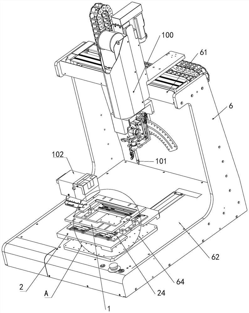
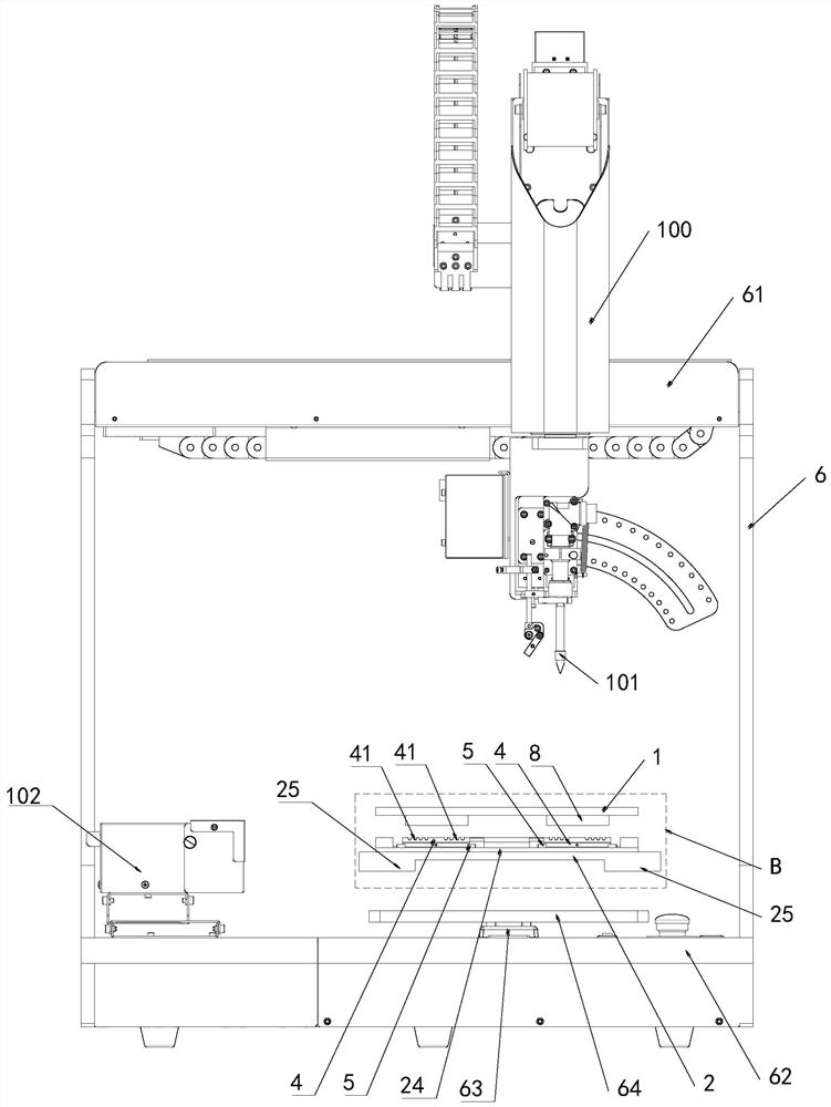
[0005]The beneficial effects of the present invention are: the present invention can lock and fix the jumper wire positioning tool on the lock by setting the locking bottom plate on the support plate under the automatic welding equipment. Tighten the bottom plate, and then use the automatic welding equipment on the beam on the top of the bracket to automatically weld the jumper wires on the jumper wire positioning tool, which can solve the problem of difficult soldering positioning of jumper wires on printed boards, large quantities, and large batches. The problem of using hand-held welding in the scene is time-consuming, high cost, and low production efficiency

Method used


Image

  • Automatic jumper wire welding device and method
  • Automatic jumper wire welding device and method
  • Automatic jumper wire welding device and method

Examples


Embodiment Construction

[0048] The principles and features of the present invention are described below in conjunction with the accompanying drawings, and the examples given are only used to explain the present invention, and are not intended to limit the scope of the present invention.

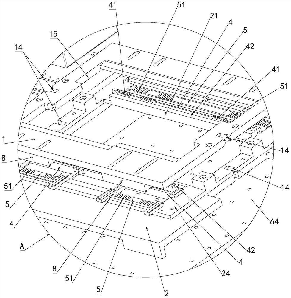
[0049] The printed board assembly hollow 21 in the middle of the printed board assembly frame 24 is used as the center of the jumper wire 91, which is also the front end of the placement orientation of the jumper wire 91, and the outer sides of the printed board assembly hollow 21 are used as the jumper wire 91. At the rear end, the jumper wires 91 are arranged around the printed board assembly hollow 21, that is, the jumper wires 91 are placed around the printed board assembly hollow 21, so that the front end 92 of the wires of the jumper wires 91 faces close to the printed board assembly The direction of the hollow 21 is extended so that the wire rear end 93 of the jumper wire 91 is extended in a direction away fro...


PUM


Abstract

The invention relates to an automatic jumper wire welding device and method.The welding device comprises a support, automatic welding equipment, a locking bottom plate and a jumper wire positioning tool, the automatic welding equipment is installed on an assembly cross beam at the top of the support, and the jumper wire positioning tool is installed on an assembly platform at the bottom of the support; a supporting block is arranged on the assembling platform, a horizontally-arranged supporting plate is installed on the supporting block, the locking bottom plate is assembled on the supporting plate, a locking mechanism is further arranged on the edge of the peripheral side of the locking bottom plate, and the jumper wire positioning tool is locked and positioned on the locking bottom plate through the locking mechanism. The jumper wire positioning tool can be locked and fixed on the locking bottom plate, and a jumper wire on the jumper wire positioning tool is automatically welded by using automatic welding equipment on the assembly cross beam at the top of the bracket; the problems of high time consumption, high cost and low production efficiency of handheld welding in an application scene that jumper wires on a printed board are difficult to weld and position, large in quantity and large in batch can be solved.

Description

technical field [0001] The invention relates to the field of automatic welding of jumper wires, in particular to an automatic jumper wire welding device and method. Background technique [0002] In the process of connecting printed boards to printed boards, it is usually necessary to use jumper wires for soldering. During automated soldering, the relative position of the jumper wire to the pad will affect the soldering quality. Moreover, the working method of the automatic welding equipment is that the tip of the soldering iron is lowered to the pad, and the tin feeding mechanism sends the solder to the jumper wire for welding. Whether the welding line is located at the position of the pad or the pressing of the tip of the soldering iron will make the welding line deviate from the position, etc., which is serious. Affect the qualified rate of welding quality of welding wire. Hand-held soldering is time-consuming, costly, and low-production in scenarios where printed board ...

Claims


Application Information

Patent Timeline
Patent Type & Authority Applications(China)
IPC IPC(8): B23K3/00B23K3/08B23K37/04
CPCB23K3/00B23K3/087B23K2101/42Y02E60/10
Inventor 张明亮卞玉柱王季熊强麻思达陈朝峰
Owner BEIJING INST OF RADIO MEASUREMENT
Learn More