Pressure control valve

A pressure regulating valve and pressure regulating chamber technology, applied in the field of pressure regulating valves, can solve the problems of reducing the capacity of the pot, increasing the structural volume of the pressure reducing valve, etc., and achieve the effect of reducing the installation space and large space

Inactive Publication Date: 2009-02-11
THOMAS SA
View PDF8 Cites 0 Cited by
  • Summary
  • Abstract
  • Description
  • Claims
  • Application Information

AI Technical Summary

Problems solved by technology

Certain compensations can indeed be achieved by selecting the piston surface as large as possible in the area of ​​the surge chamber, so that the axial end face of the piston rod becomes, for example, a less important disturbance variable; however, this requires significant Increased structural volume of the pressure reducing valve, which equates to a reduction of the maximum possible pot capacity

Method used


Image

  • Pressure control valve
  • Pressure control valve
  • Pressure control valve

Examples


Embodiment Construction

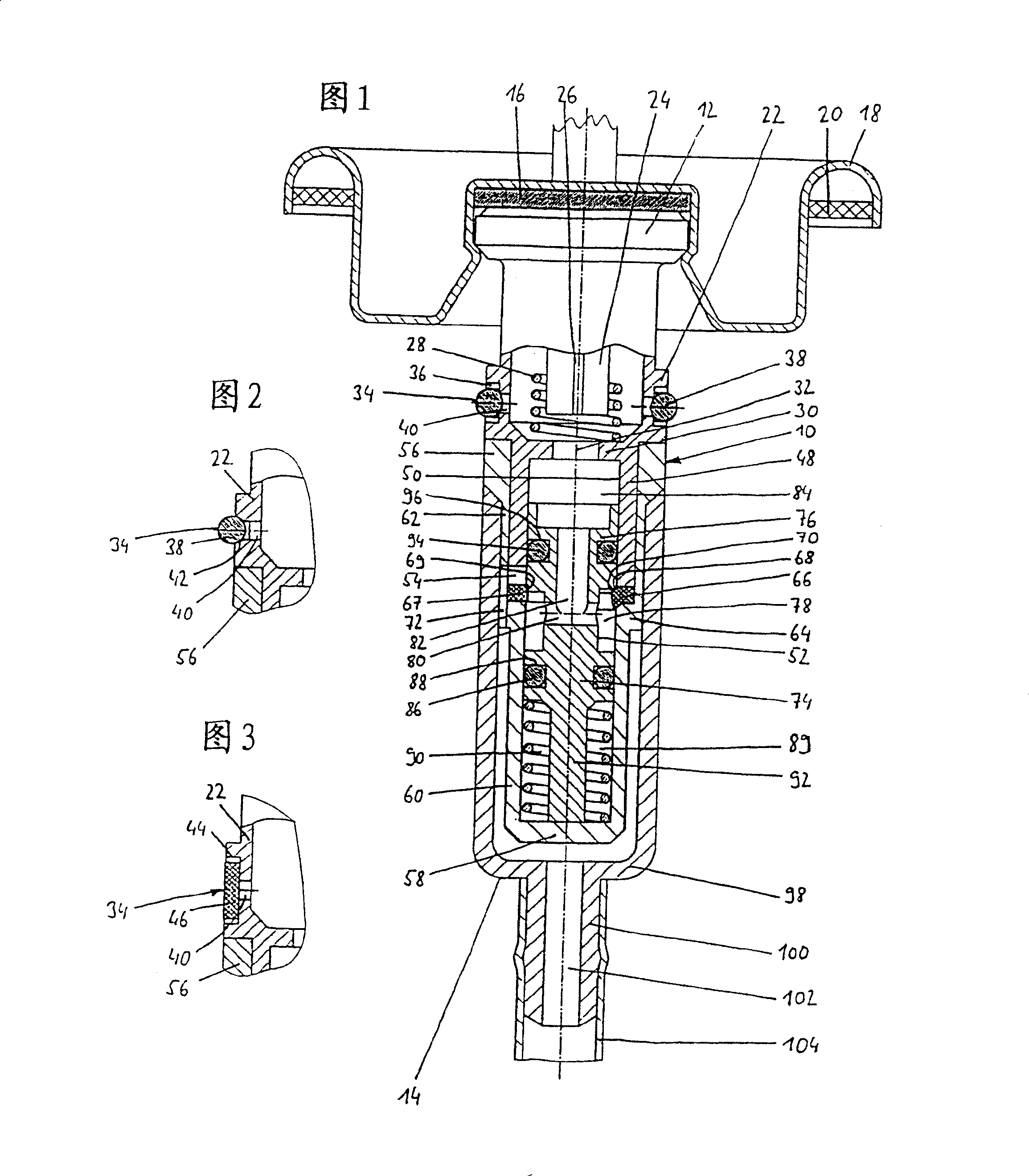
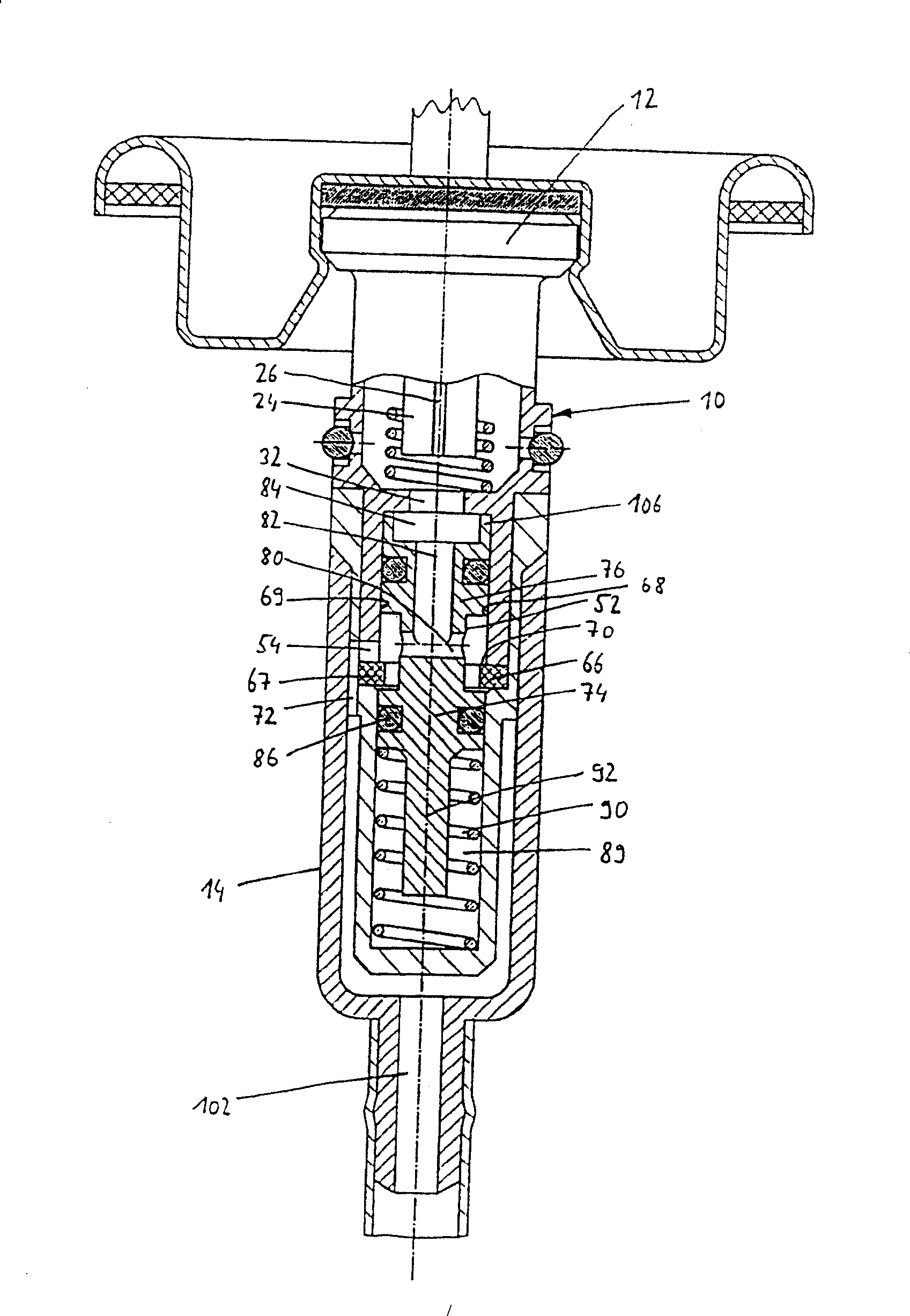
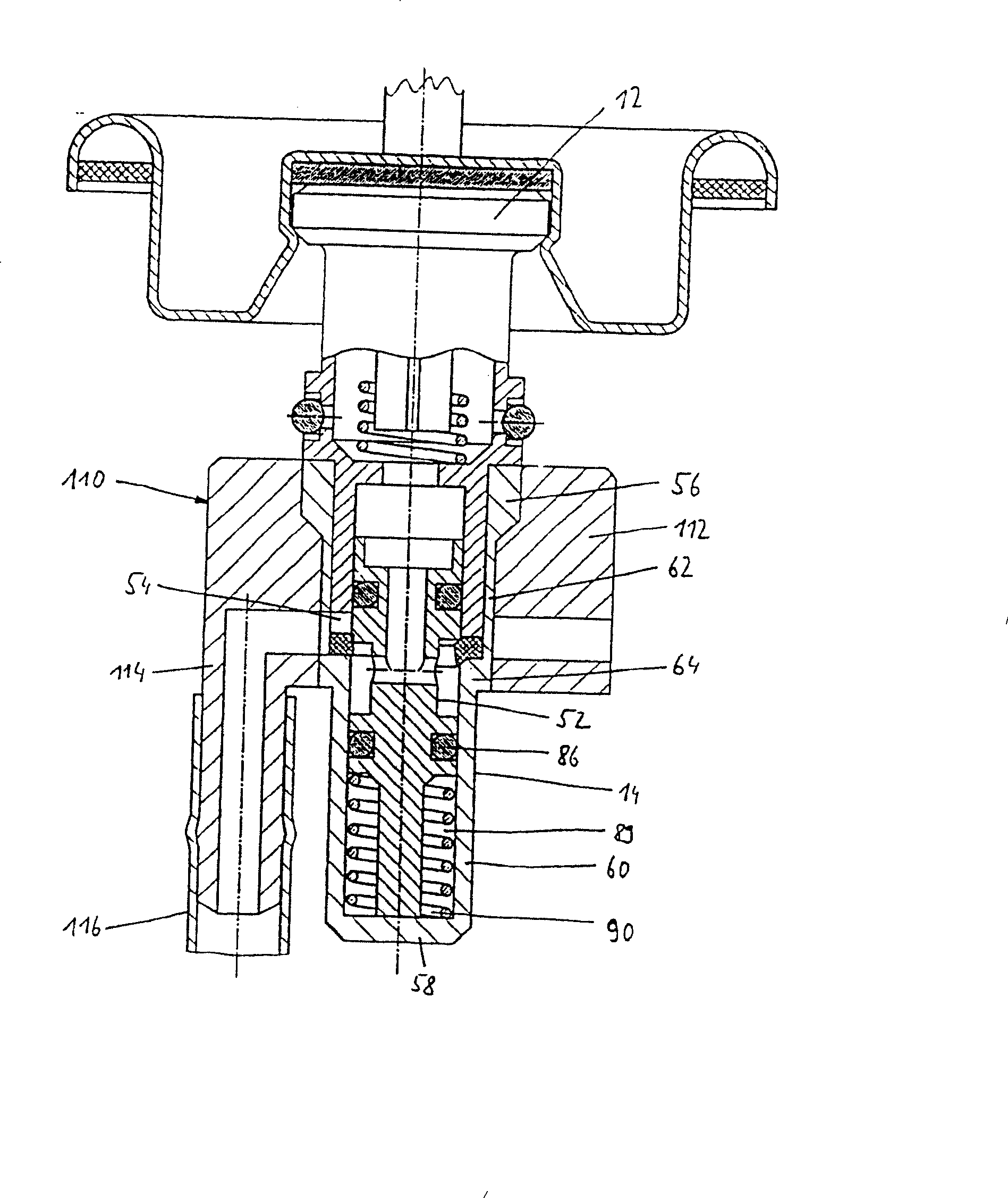
[0027] FIG. 1 shows a combined unit 10 comprising a spray valve 12 and a pressure regulating valve 14 . In its internal structure, the spray valve 12 corresponds to a conventional spray valve and its details are therefore not shown. This unit with the spray valve 12 is pre-assembled on a valve disc 18 and is sealed in a known manner with a sealing plate 16; the valve disc is then hermetically fixed to a watering can body with a sealing ring 20 on (not shown in the figure).

[0028]The spray valve has a spray valve housing 22 in which a stem 24 has an end 26 and a through hole and is movable against the load of a compression spring 28 . The spray valve housing 22 has an intermediate wall 30 with a through hole 32 , which separates the spray valve 12 from the pressure regulating valve 14 . In the wall of the spray valve housing 22 is provided an overpressure charging valve 34, which basically comprises an annular sealing element 38, which is arranged in a pretensioned manner i...


PUM


Abstract

A pressure regulating valve reduces the increased internal pressure in an aerosol spray can, filled with compressed gas, to a working pressure level for a spray valve (12). A regulating piston (52) is kept in equilibrium by a restoring force, and a sealing point (66, 68) is provided, which is closed at a pressure in the pressure regulation chamber (84) that is above the regulated pressure level. To prevent the precision of regulation from being adulterated by the decreasing internal pressure of the can as its contents are progressively withdrawn, a sealing means (86, 66; 67) is proposed, which seals off one free end of the piston (52, 74) from the internal pressure of the can and the regulated pressure. The variable internal pressure of the can is therefore no longer able to act on any axial face of the piston (52), and despite what may be a smaller piston face area, the precision of regulation is improved.

Description

technical field [0001] The invention relates to a pressure regulating valve. Background technique [0002] Such pressure regulating valves are used in aerosol spray cans which operate without propellant gas, that is to say without chemical aerosol propellants; wherein the abandonment of the use of such a propellant gas makes it necessary to fill the aerosol spray can to a significant high pressure , such as 10bar. Since the spray valve operates at a defined low pressure level, which is also the case with the aerosol watering cans with propellant gas filling used so far, and the remaining part of the watering can should be emptied as far as possible, a pressure regulating valve is required. It is located before the spray valve and can reduce the internal pressure of the watering can to a pressure suitable for the spray valve, such as 3bar. Pressure regulating valves of the type mentioned at the outset are described, for example, in WO 01 / 09009 A1, EP 0 931 734 A1 and WO 01 / ...

Claims


Application Information

Patent Timeline
IPC IPC(8): B65D83/14B65D83/44B05B9/04B65D3/14
CPCB65D83/52Y10T137/8704Y10T137/7808
Inventor H·施奈德
Owner THOMAS SA
Why Eureka
Try Eureka