Vehicular display device

A display device and display design technology, which is applied to vehicle components, measurement value indication, and simultaneous indication of the values ​​of multiple variables, etc., can solve the problem of lack of aesthetic decorative appearance of vehicle display devices.

Inactive Publication Date: 2009-02-11
DENSO CORP +1
View PDF6 Cites 0 Cited by
  • Summary
  • Abstract
  • Description
  • Claims
  • Application Information

AI Technical Summary

Problems solved by technology

[0009] This causes a problem that the car display device lacks an aesthetically pleasing decorative appearance

Method used


Image

  • Vehicular display device
  • Vehicular display device
  • Vehicular display device

Examples


no. 1 example

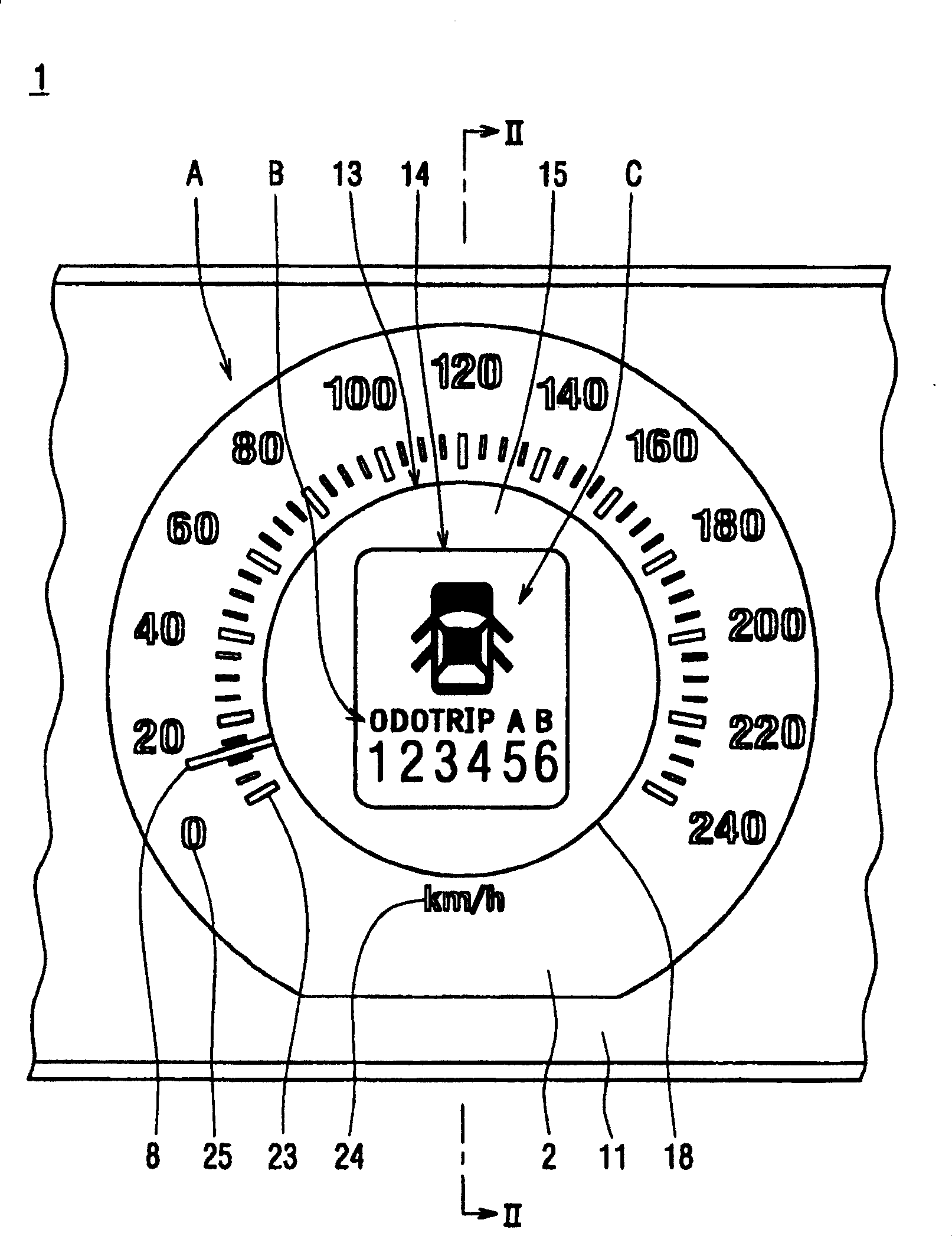
[0032] figure 1 is a partial front view of the combination meter 1 according to the first embodiment of the present invention.

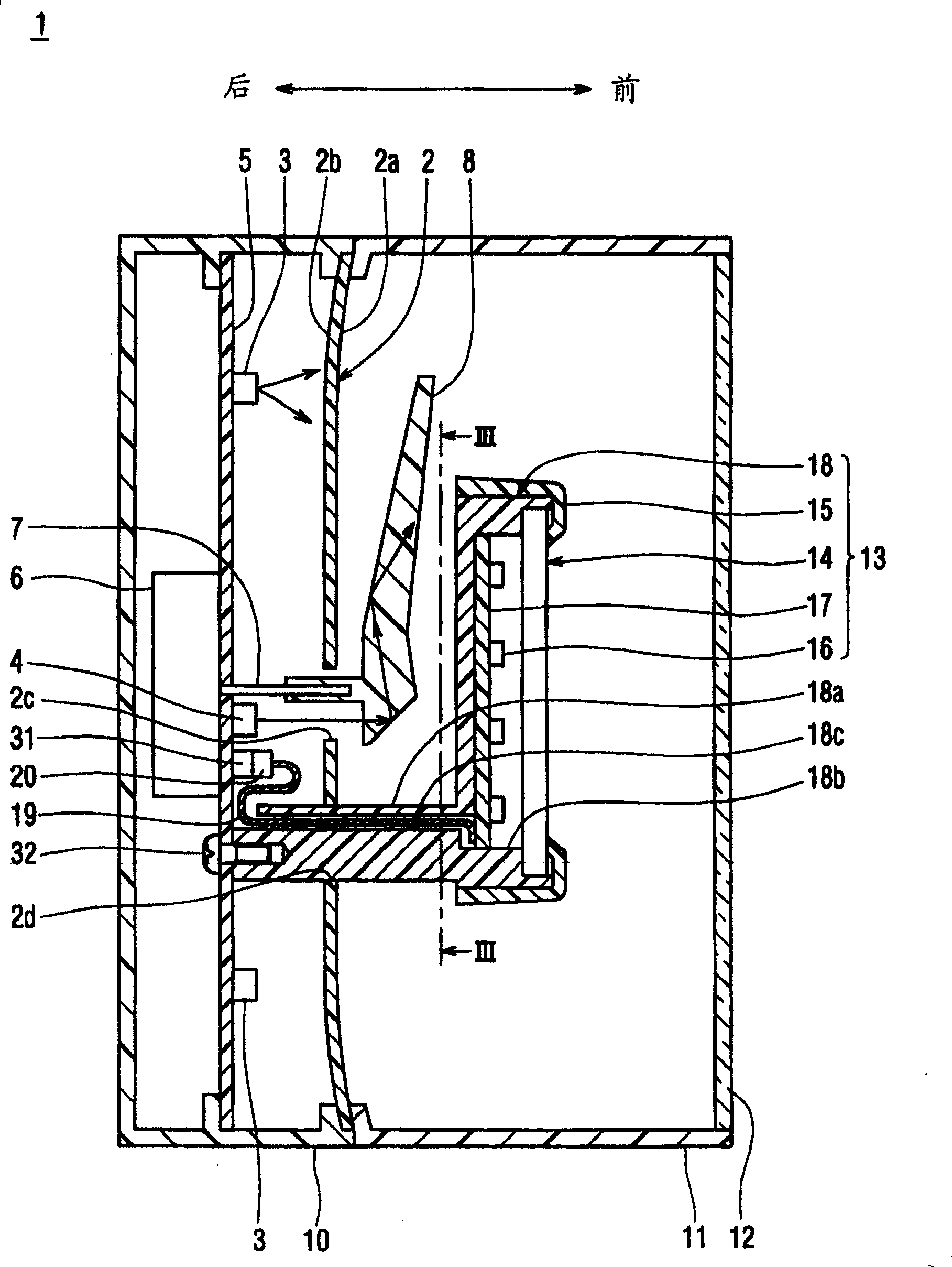
[0033] figure 2 is along figure 1 Sectional view taken along midline II-II. exist figure 2 In , the right side surface faces the driver's seat from which the combination meter 1 is visible.

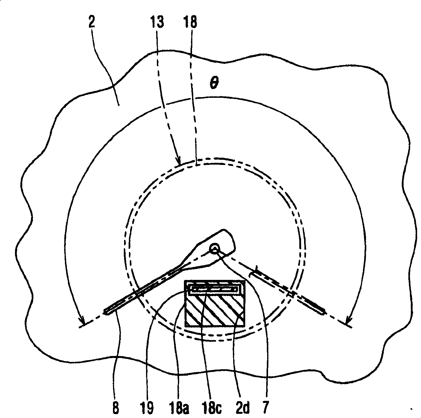
[0034] image 3 is a view illustrating the inner surface of the combination meter 1 . exist image 3 In , scales 23, characters 24 and numbers 25 are omitted for ease of understanding.

[0035] Figure 4 is a simplified diagram illustrating the circuit configuration of the combination meter 1.

[0036] The combination meter 1 is installed in the vehicle so that the driver in the driver's seat can observe the combination meter 1 . The combination meter 1 displays various information related to the vehicle. The combination meter 1 includes a speedometer A indicating the traveling speed of the vehicle, a rangefinder B indicating the accumulated travelin...

no. 2 example

[0071] Figure 5 is a sectional view of the combination meter 1 according to the second embodiment and corresponds to the figure 1 Sectional view taken along midline II-II.

[0072] The combination meter 1 according to the second embodiment differs from the first embodiment in the fixing of the center panel 13 to the speedometer A. As shown in FIG.

[0073] like Figure 5 As shown, the supporting plate 40 is provided as a supporting unit to support and fix the central panel 13 . The support plate 40 is formed of a transparent material such as transparent polycarbonate. The support plate 40 is in the viewing direction ( Figure 5 in the horizontal direction) is closer to ( Figure 5 middle right) observer. In detail, the reflector 18 is fitted in the engagement hole 40 a provided in the support plate 40 .

[0074] The reflector 18 has a guide portion 18d instead of the attaching portion 18a of the first embodiment, as Figure 5 shown. The guide portion 18d includes a c...

no. 3 example

[0078] Image 6 is a sectional view of the combination meter 1 according to the third embodiment and corresponds to the figure 1 Sectional view taken along midline II-II.

[0079] The combination meter 1 according to the third embodiment differs from the second embodiment in the structure of the support plate 40 . The characters 24 and numerals 25 of the display design in the speedometer A are formed on the support plate 40.

[0080] like Image 6 As shown, characters 41 and numerals 42 are formed on the rear surface 41 of the support plate 40 by forming an opaque colored layer or a translucent colored layer using printing or hot stamping.

[0081] In addition, light-emitting diodes 45 are installed on the printed circuit board 17 of the central panel 13 as light sources for illuminating characters 41 and numbers 42, such as Image 6 shown.

[0082] Combination meter 1 according to the third embodiment can provide the same effects as those of the first embodiment. The ce...


PUM


Abstract

A center panel (13) is closer to a viewer in the viewing direction than a speedometer A is and overlapped with the speedometer (A). The center panel (13) includes an attachment portion (18a) extending from a rear side of the center panel (13) towards a dial plate (2) of the speedometer (A). The center panel (13) is fixed to a printed circuit board (5) of the speedometer (A) via the attachment portion (18a). Accordingly, when a combination meter (1) is viewed, the attachment portion (18a) is concealed rearward of the center panel (13) to be invisible. The center panel (13) looks floating separately from the speedometer (A) towards a viewer, which provides a combination meter (1) having excellent visibility and aesthetic cosmetic appearance. Thus, a vehicular display device having excellent visibility and aesthetic cosmetic appearance can be provided by improving a method for supporting a displaying unit on a pointer instrument.

Description

technical field [0001] The present invention relates to a display device for a vehicle that displays various information to the driver near the driver's seat. Background technique [0002] Recently, the number of information items displayed in display devices for vehicles has increased. In addition to display devices, the number of components such as air conditioners and air bags installed in instrument panels has also increased. Therefore, display devices are required to become smaller. [0003] Therefore, the display device needs to satisfy two requirements at the same time, that is, increase and decrease the number of displayed information items or categories; these two requirements conflict with each other. [0004] In order to meet these requirements, Patent Document 1 discloses a display device including a pointer meter and a display unit, which displays given information to the driver. At least the pointer end portion of the pointer meter is exposed outside the disp...

Claims


Application Information

Patent Timeline
Patent Type & Authority Patents(China)
IPC IPC(8): G01D7/00G01D11/26B60K35/00G01D7/04
CPCB60K2370/336B60K2370/698
Inventor 角屋实栗川庄治荒木良德今井丰村松芳幸
Owner DENSO CORP
Why Eureka
Try Eureka