Lamp and lamp holder with peripheral locking means

A lamp holder and lamp cap technology, which is applied to the parts, coupling devices, lighting devices, etc. of lighting devices, and can solve the problems of unsightly positioning of illuminants and/or light sources, etc.

Inactive Publication Date: 2009-02-25
KONINKLIJKE PHILIPS ELECTRONICS NV +1
View PDF7 Cites 0 Cited by
  • Summary
  • Abstract
  • Description
  • Claims
  • Application Information

AI Technical Summary

Problems solved by technology

However, a disadvantage of the lighting device disclosed in said US patent is that the bulb is not always positioned in the lamp socket in the same way, resulting in a less than optimal use of the luminaire and / or an unattractive positioning of the light source

Method used


Image

  • Lamp and lamp holder with peripheral locking means
  • Lamp and lamp holder with peripheral locking means
  • Lamp and lamp holder with peripheral locking means

Examples


Embodiment Construction

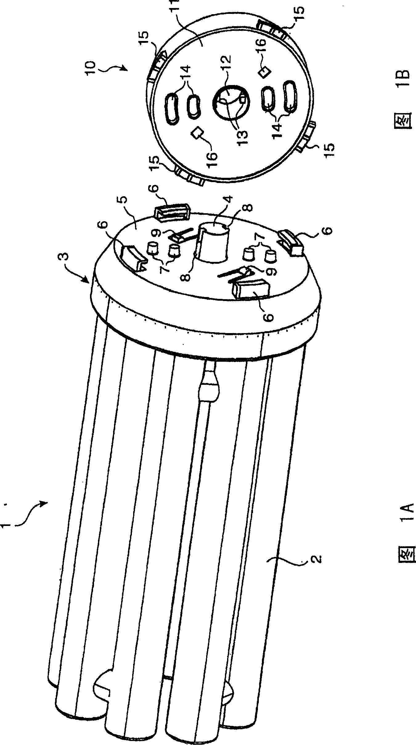
[0015] FIG. 1A shows a discharge lamp 1 with a tubular discharge vessel 2 comprising electrodes, not shown, in order to create a discharge channel. The lamp 1 also has a lamp cap 3 for holding the discharge vessel 2 and the electrodes, with a central protrusion 4 remote from the discharge vessel 2 . The protruding portion 4 is surrounded by the cap surface 5 by a peripheral engaging hook 6 (also called locking engaging portion 6). The lamp cap 3 also holds the contact pins 7 (also referred to as contact members 7 ) in a direction parallel to the projection 4 and also away from the discharge vessel 2 . The keyway 8 on the protrusion 4 will be described with reference to FIG. 2 . The lamp base 3 also has a clip 9 elastically connected to the surface 5 of the lamp base. Although the above description refers only to discharge lamps, the lamp according to the invention may also be an incandescent lamp.

[0016] In order to operate the lamp 1, the contact pin 7 must be brought in...


PUM


Abstract

The invention relates to a lamp comprising a bulb (2) and a base (3), the base (3) comprising a protruding portion (4) located substantially in the center of the base (3) and extending in a direction away from the bulb (2) , at least one locking portion (6), and a generally flat base surface (5) opposite to the bulb (2) and surrounding the protruding portion (4), characterized in that there is at least one locking engagement portion (6), Located on the edge of the cap surface (5) of the surrounding projection (4) remote from said central projection, the invention also relates to a lamp holder (10) for cooperating with a lamp (1) according to the invention, a lamp holder (10 ) comprising a hole (12) substantially centrally located in the lampholder (10), at least one reversing locking engagement portion (15), and a substantially flat lampholder surface (11) surrounding said hole, characterized in that at least There is a reverse locking engagement portion (15) located on the edge of the socket surface (11) surrounding the hole (12), remote from said central hole (12).

Description

technical field [0001] The present invention relates to a lamp comprising a bulb and a base comprising a protruding portion located substantially centrally in the base and extending in a direction away from the bulb, at least one locking engagement portion, and a The substantially flat cap surface of the protruding portion. The invention also relates to a lampholder for cooperating with a lamp according to the invention, said lampholder comprising an aperture substantially in the center of the lampholder, at least one reversing locking engagement portion, and a substantially flat lamp surrounding said aperture. surface of the lamp holder. Background technique [0002] US Patent 5,746,615 discloses a light emitting device, particularly adapted to emit light, having a cap at one end of a bulb, and a single-ended lamp socket into which said cap is inserted and then twisted so that it rotates with said socket join. The lamp has a protruding portion and a lamp pin protruding f...

Claims


Application Information

Patent Timeline
Patent Type & Authority Patents(China)
IPC IPC(8): F21V19/00H01R33/08F21S2/00F21Y103/37H01J5/48H01R33/46H01R33/76
CPCF21V19/006H01R33/46H01R33/0809H01R33/7692F21V19/0095H01J61/00H01R33/08
Inventor J·W·F·多雷恩N·G·A·皮特斯M·皮珀K·-W·沃格特
Owner KONINKLIJKE PHILIPS ELECTRONICS NV
Why Eureka
Try Eureka