
A cylinder cleaning apparatus

A technology of equipment and cylinders, applied in office printing equipment, printing, printing presses, etc., can solve problems such as laborious and time-consuming cleaning

Inactive Publication Date: 2009-03-04
BALDWIN JAPAN LTD
View PDF6 Cites 2 Cited by
  • Summary
  • Abstract
  • Description
  • Claims
  • Application Information

AI Technical Summary

Problems solved by technology

As a result, the operator must laboriously and time-consumingly clear the drain pipe clogged with sludge and may need to replace the drain pipe with a new one

Method used


Image

  • A cylinder cleaning apparatus
  • A cylinder cleaning apparatus
  • A cylinder cleaning apparatus

Examples


Embodiment Construction

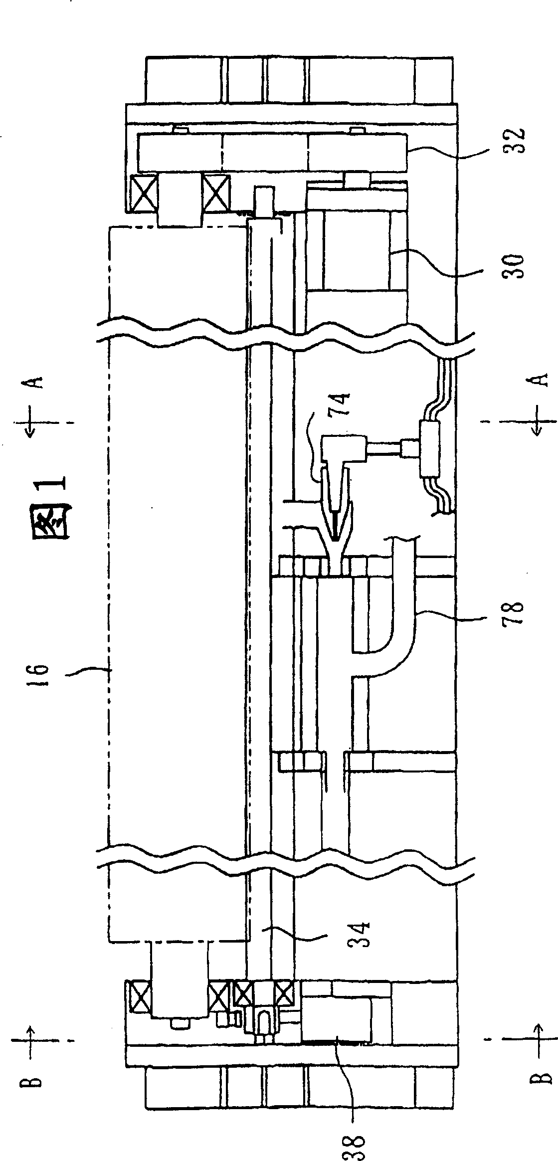
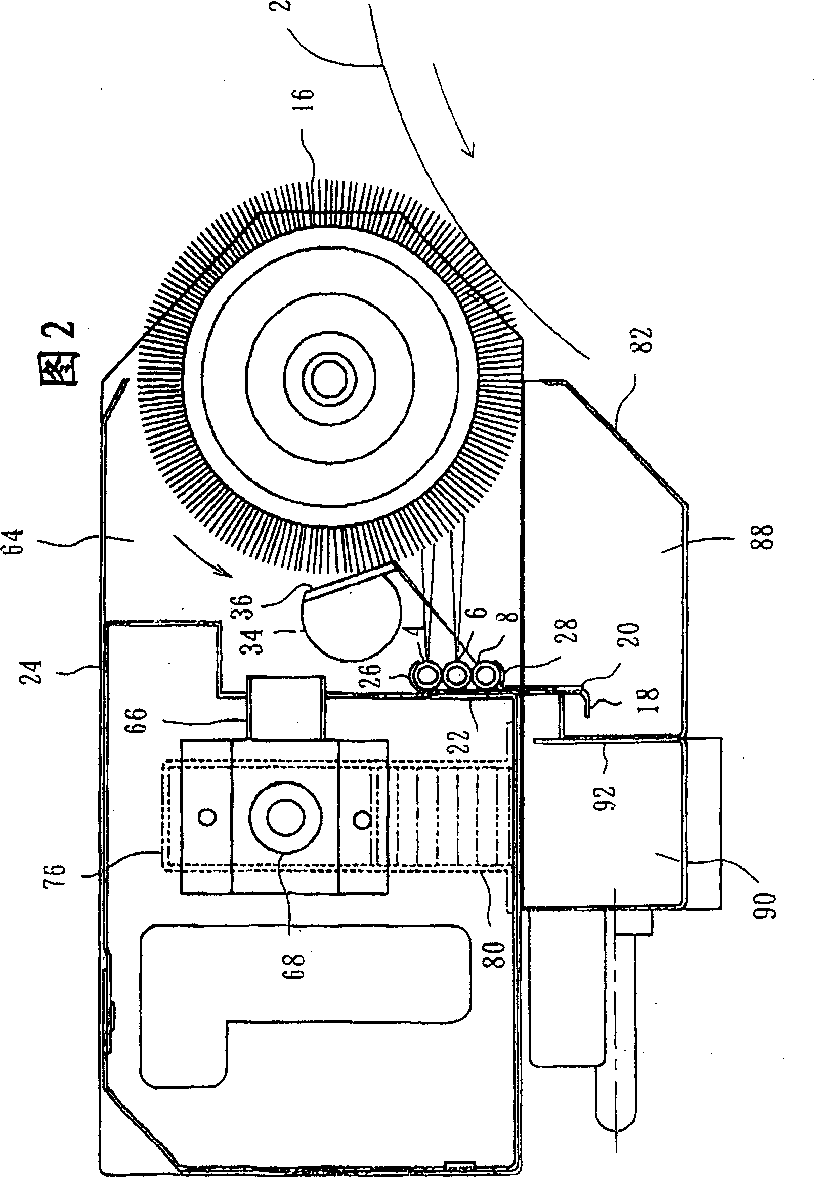
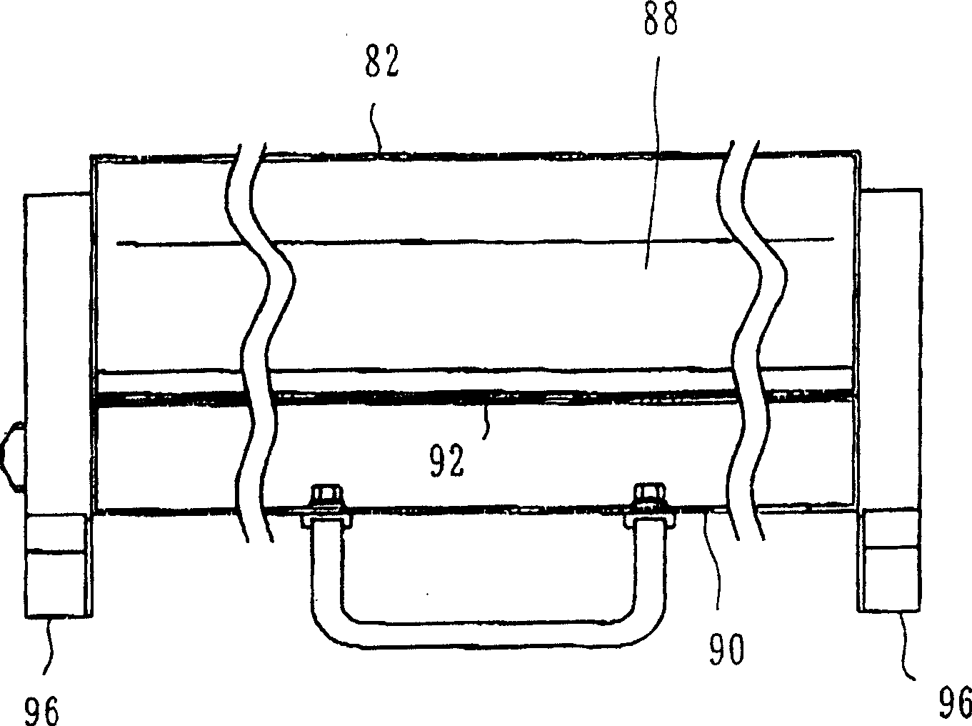
[0050] Referring now to the drawings, Figure 1 shows an apparatus according to the invention for cleaning a cylinder 2 in an offset or other printing press as shown in Figure 2, by means of a supply of cleaning fluid. The drum 2 includes an outer surface to which impurities such as dry ink, lint, and the like adhere. Impurities are removed from the outer surface during cleaning.

[0051] The device consists of a boom into which cleaning fluid is introduced under pressure. The spray bar comprises a pipe arrangement comprising a plurality of pipes 4, 6 and 8, said pipe arrangement comprising spray holes 10 formed thereon for spraying cleaning fluid, such as Figure 8 shown. Tubes 4, 6 and 8 are made of elastic and flexible material such as polyurethane, nylon, fluororesin (Teflon), silicone rubber, polyethylene or other high polymer. The orifices 10 include pinholes each formed in the tubes 4, 6 and 8 by penetrating the tubes 4, 6 and 8 with a needle 12, as shown in FIG. There...


PUM


Abstract

An apparatus is arranged to clean a cylinder with cleaning liquid being supplied. The cylinder includes an outer surface to which impurities are adhered. The impurities are removed from the outer surface when cleaning. The apparatus includes a spray bar into which the cleaning liquid is directed with pressure. The spray bar comprises tube means which Includes nozzle holes formed therein for spouting the cleaning liquid. The tube means is formed of elastic material and elastically deformed by the pressure of cleaning liquid to open the nozzle holes and spout the cleaning liquid. The tube means is elastically restored, when the cleaning liquid is not directed with pressure into the spray bar, to close the nozzle holes.

Description

technical field [0001] The present invention relates to an apparatus for cleaning cylinders in offset printing presses, other printing machines, paper machines, converted paper machines, textile machines and the like. The drum includes an outer surface to which impurities are attached, from which the impurities are removed when washing. Background technique [0002] For example, foreign matter such as dry ink, lint, etc. adheres to the outer surface of the cylinder of an offset press or other printing presses. Therefore, it is necessary to clean the cylinder regularly to ensure the good quality of each printed product. [0003] In this case, an apparatus for washing a drum with a washing liquid as disclosed in US Pat. No. 5,109,770 is commercially available. In the apparatus of this US patent, cleaning fluid is introduced under pressure into the boom. The boom consists of a tube with holes directed towards the brush roll for spraying cleaning fluid. The brush roll is bro...

Claims


Application Information

Patent Timeline
Patent Type & Authority Patents(China)
IPC IPC(8): B41F35/06B41L41/06B05B1/14B41F35/00B41F35/02
CPCB41P2235/23B41P2235/26B41F35/00B41F35/06
Inventor 西山荣造吉田和弘
Owner BALDWIN JAPAN LTD
Learn More