A rubber crawler

A technology of rubber crawler and rubber elastic body is applied in the field of rubber crawler, which can solve the problems of operator vibration, bringing into the joint hole, and the runner 10 moving up and down, so as to improve the propulsion force, avoid the up and down movement, and prevent vibration. Effect

Inactive Publication Date: 2009-03-04
BRIDGESTONE CORP
View PDF5 Cites 0 Cited by
  • Summary
  • Abstract
  • Description
  • Claims
  • Application Information

AI Technical Summary

Problems solved by technology

[0004] However, this prior art rubber crawler track has its disadvantages - causing vibration to the operator, and bringing mud lumps into the joint hole 5 from the ground
The former is due to the fact that the runner 10 rolling on the inner peripheral surface of the rubber crawler is located at the position on the teeth 4a, 4b and at a position between them alternately. The condition and the condition away from it alternately occur, so the supported and unsupported conditions for the contact surface also alternately occur, thus causing the runner 10 to move up and down, making the vibration unavoidable
[0005] In addition, since the mud adhering to the vicinity of the joint hole 5 is pressed and solidified by the drive sprocket 20, it becomes a mud ball and falls to the outside, so the mud ball may fall on other objects, which is a bad phenomenon.

Method used


Image

  • A rubber crawler
  • A rubber crawler
  • A rubber crawler

Examples


Embodiment Construction

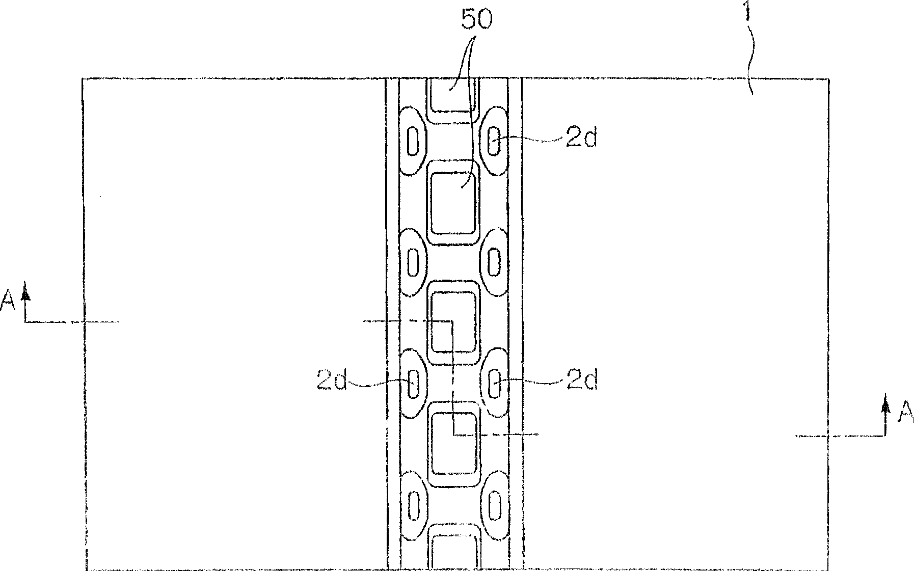
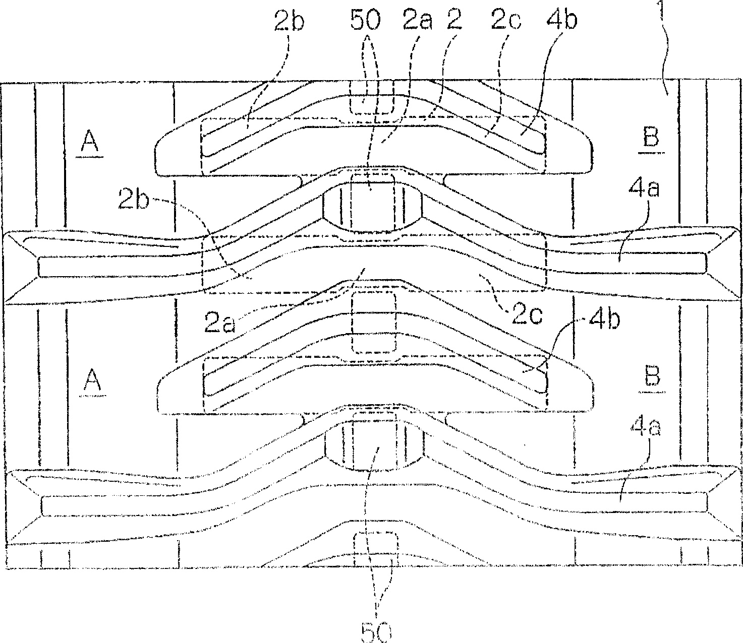
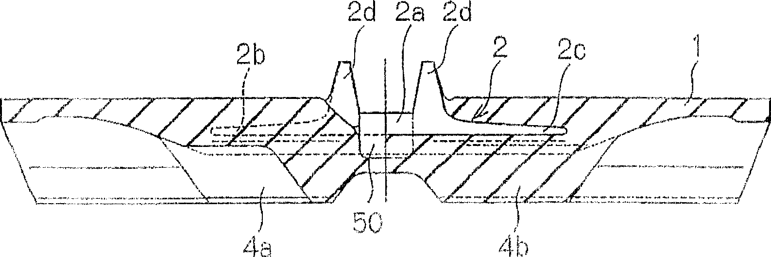
[0022] The rubber track of the present invention will be described in more detail based on the examples below. figure 1 It is the inner peripheral side plan view of the 1st example of the rubber crawler of this invention. figure 2 yes figure 1 A top view of the outer peripheral side of the rubber track. image 3 is along figure 1 A cross-sectional view taken along line A-A. in addition, Figure 4 is an enlarged cross-sectional view along the longitudinal direction of the concave portion. Figure 5 It is an enlarged cross-sectional view along the width direction of the above-mentioned concave portion.

[0023] In the figure, 1 is a rubber elastic body constituting the base of the rubber track, which is connected in a ring shape in the vertical direction in the figure. 2 is a core member embedded in the rubber elastic body, which is embedded at a fixed interval along the length direction of the rubber elastic body 1. The left and right wing parts 2b, 2c of the core mem...


PUM


Abstract

A rubber crawler running mainly on a damp ground and capable of eliminating the production of mud balls passed through the engagement holes thereof with the teeth of sprockets and reducing vibration, comprising an endless rubber elastic body, cores buried therein at specified pitches in the longitudinal direction, steel cords surrounding the cores from the outside, the engagement parts thereof with the sprockets formed between the cores, and lugs formed on the outer peripheral surface of the endless rubber elastic body. The engagement parts thereof with the sprockets are characterized by bottomed recesses formed therein. The lugs are desirably formed on the outsides of the bottomed recesses.

Description

technical field [0001] The invention relates to a novel structure of a rubber track, in particular to a rubber track mainly used for running on wet ground. Background technique [0002] In a rubber crawler track suitable for running on wet ground, core members are buried at fixed intervals along the length direction of the annular rubber elastic body, steel cords are wound on the outside of the core member, teeth are formed on the outside of the rubber elastic body, and teeth are formed on the outside of the core member. Engaging holes are formed through the inside and outside of the rubber elastic, which are engaged with the drive sprocket. [0003] Figure 8 It is a top view of the inner peripheral side of the rubber track that has been widely used. Figure 9 It is the top view of the peripheral side Figure 10 is along Figure 8 The cross-sectional view taken along the line B-B in the center. 1 is a rubber elastomer, in Figure 8 The center is continuous up and down th...

Claims


Application Information

Patent Timeline
Patent Type & Authority Patents(China)
IPC IPC(8): B62D55/253B62D55/24
CPCB62D55/244B62D55/125B62D55/253
Inventor 下园靖夫
Owner BRIDGESTONE CORP
Why Eureka
Try Eureka