
A polarity testing device of electronic elements of automatic braiding machines and a testing method thereof

An automatic braiding machine and polarity detection technology, which is applied in the direction of measuring devices, instruments, packaging, etc., to achieve the effects of cost reduction, simple and compact devices, and scientific and reasonable detection methods

Inactive Publication Date: 2009-03-04
TIANJIN UNIV OF SCI & TECH
View PDF6 Cites 0 Cited by
  • Summary
  • Abstract
  • Description
  • Claims
  • Application Information

AI Technical Summary

Problems solved by technology

Due to the strict polarity requirements of the device braid, it is strictly required that the polarity is consistent, there must be no damaged parts, and the marked surface must face the same direction. Although the components delivered by the linear feeder can achieve the marked surface to face upwards, but The polarity reversal and the quality of the device need to be strictly inspected, and these two inspections can only be carried out simultaneously during the transfer of the device on the plate to improve work efficiency

Method used


Image

  • A polarity testing device of electronic elements of automatic braiding machines and a testing method thereof
  • A polarity testing device of electronic elements of automatic braiding machines and a testing method thereof
  • A polarity testing device of electronic elements of automatic braiding machines and a testing method thereof

Examples


Embodiment Construction

[0023] Embodiments of the present invention are described in further detail below in conjunction with the accompanying drawings:

[0024] Taking the SOT automatic taping machine as an example below, the technical composition and detection method of the present invention are described in detail.

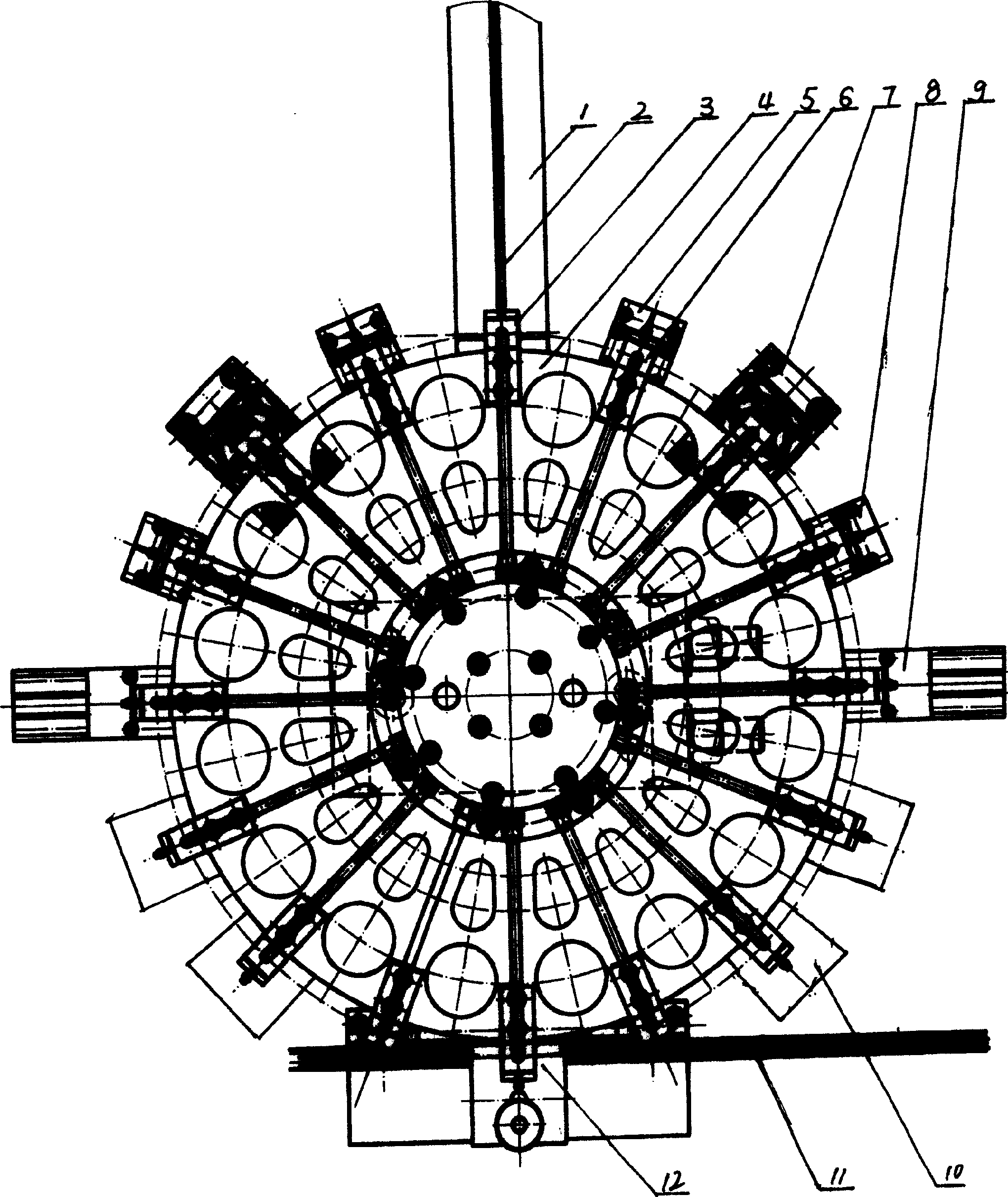
[0025] The SOT automatic tape braiding machine uses the linear feeder 1 to transport the device to the main pick-up station 3 installed at its end through the material guide groove 2, and the device is transferred to the braiding station through the suction head 6 on the swing plate. There are 12 main unloading stations in 11 places, and the finished products are finished after braiding.

[0026] The following will first describe the polarity detection device of the automatic tape machine:

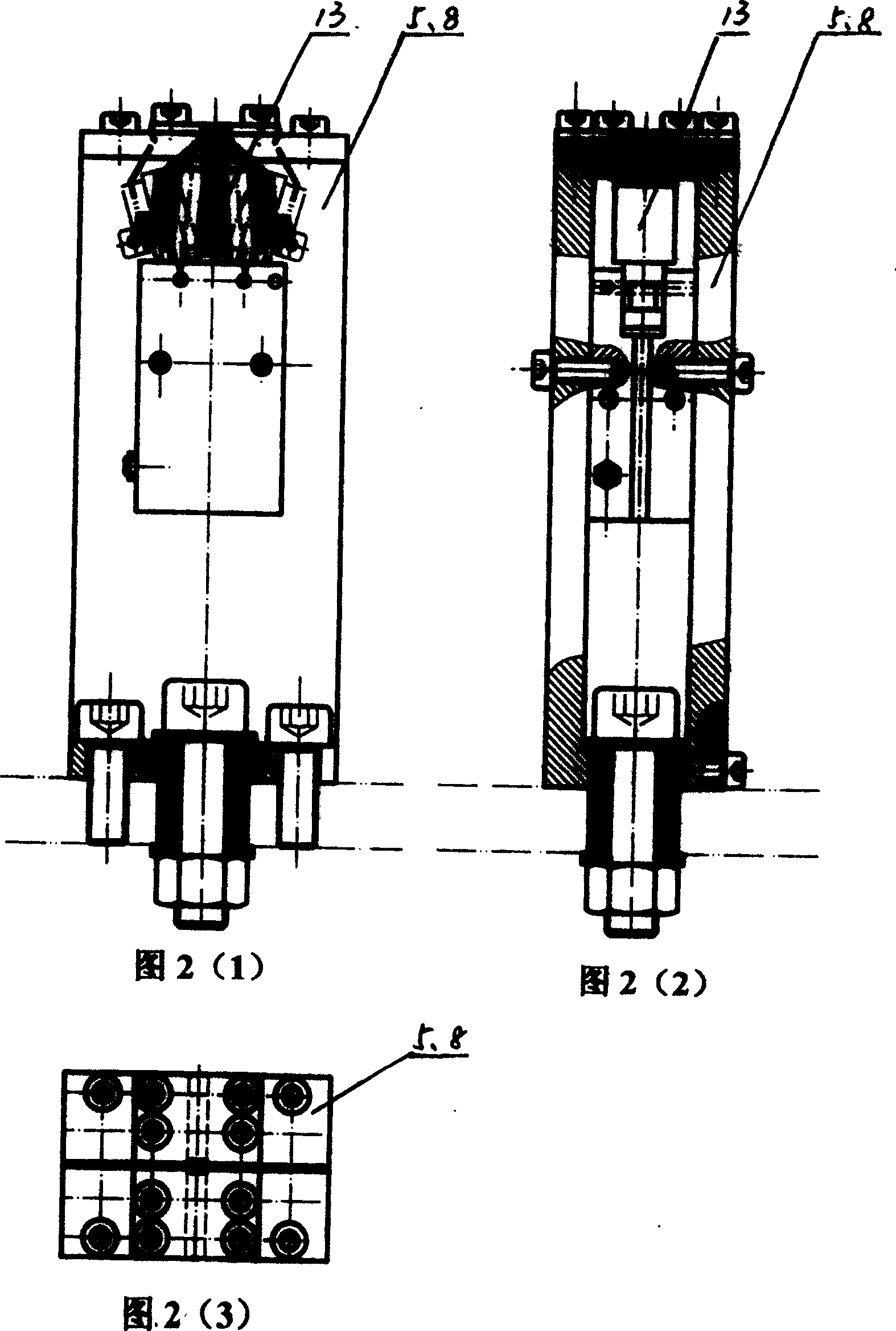
[0027] There are several vacuum suction heads evenly distributed on the outer edge of the circumference of the braiding machine's swing plate, and the suction heads of the swing plate are symmetr...


PUM


Abstract

The invention belongs to an electronic device polarity supervisory instrument and testing method of automatic braider. It characterized in that several vacuum suction nozzles are equispaced in circumference of swash plate, and divided into two groups to realize the shifting that a component is transferred from one station to the next station. The detecting station, component rotating station, quadratic detecting station of the component and component abandoning station are set symmetrically under the vacuum suction nozzles to realize the polarity detecting, polarity adjusting, quadratic polarity detecting and the abandoning of components in course of shifting that a component is transferred from one station to the next station. The whole apparatus is simple and compact, can realize synchronously the detecting in course of shifting of components, the efficiency of work is improved and the cost is decreased. The apparatus has the function of self-centering.

Description

technical field [0001] The invention belongs to an automatic braiding machine for electronic components, in particular to an automatic braiding machine electronic device polarity detection device and a detection method. Background technique [0002] For the convenience of use and transportation, to meet the needs of modern electronic equipment automatic production line assembly, electronic components generally need to be automatically taped and packaged, so the automatic taping machine came into being. For example, the SOT automatic taping machine is applied to the automatic taping and packaging of two-pole electronic components such as diodes, and is currently the most commonly used taping machine. The braiding of electronic components has strict requirements on polarity and forward and reverse directions. The sides with uniform marks must face the same direction, which is convenient for continuous use by production line users. Two-pole electronic components The two-pole e...

Claims


Application Information

Patent Timeline
Patent Type & Authority Patents(China)
IPC IPC(8): G01R31/00B65B15/04
Inventor 李振亮陈晓艳李亚许玮刘文武樊勇
Owner TIANJIN UNIV OF SCI & TECH
Learn More