

Air conditioner
An air conditioner and air conditioning technology, applied in air conditioning systems, airflow control components, space heating and ventilation, etc., can solve problems such as difficulty in setting wind direction, easy condensation, and reduced air volume
Inactive Publication Date: 2009-03-11
SHARP KK
View PDF8 Cites 0 Cited by
- Summary
- Abstract
- Description
- Claims
- Application Information
AI Technical Summary
Problems solved by technology
However, this not only reduces the air volume when it is blown horizontally or forward, but also brings about a new problem that condensation tends to occur on the horizontal louvers 11a and 11b during cooling operation.
In addition, according to the air conditioner disclosed in Patent Document 1, since the airflow is separated from the louver due to the sudden change of the airflow direction, it is very difficult to set the airflow direction in the desired direction.
Method used
View moreImage
Smart ImageViewing Examples

Examples
no. 1 Embodiment approach
no. 2 Embodiment approach
no. 3 Embodiment approach
Login to View More PUM
 Abstract
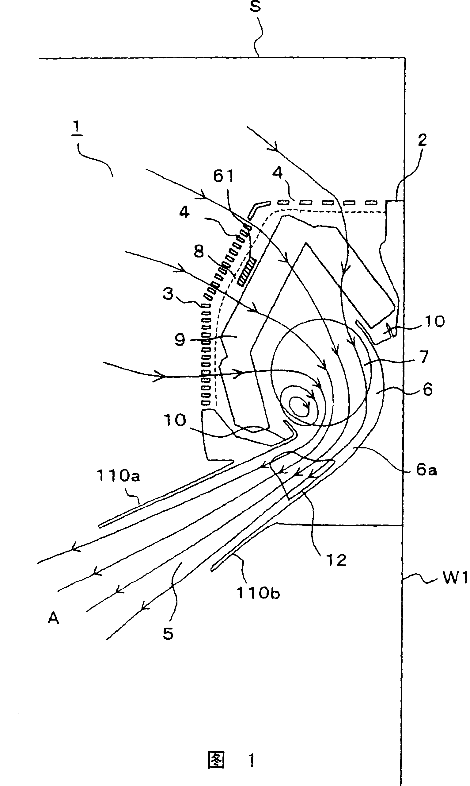
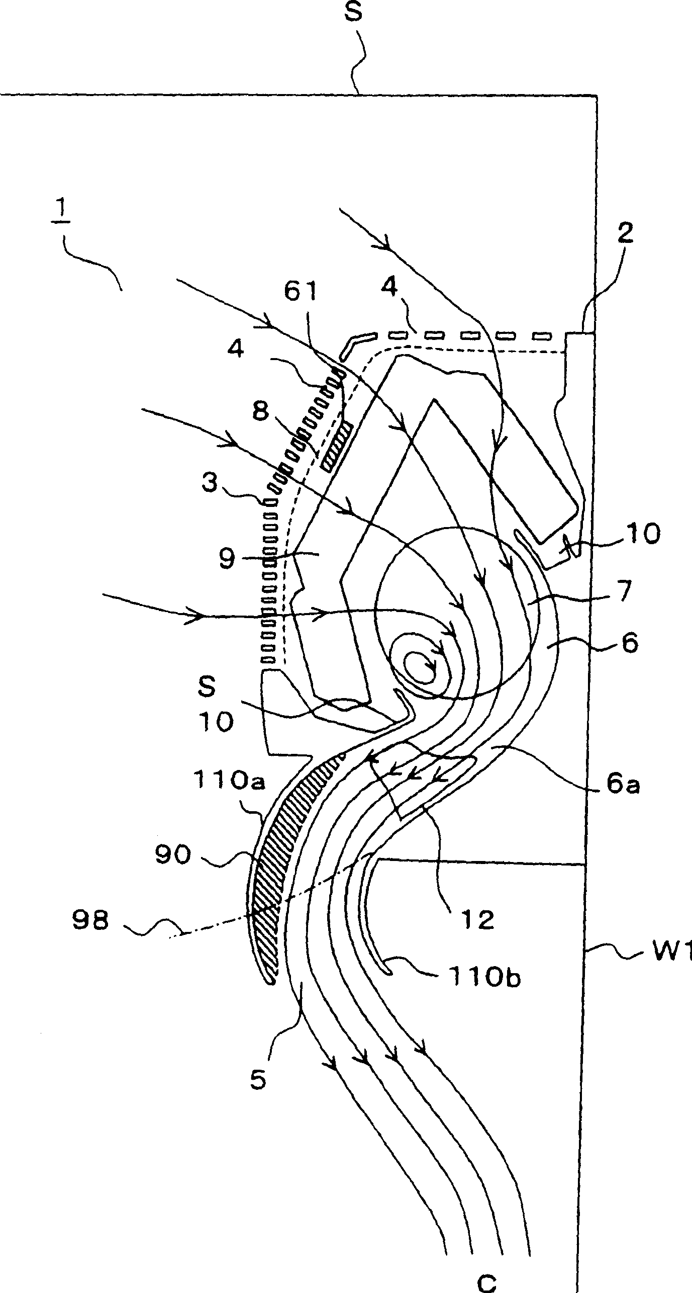
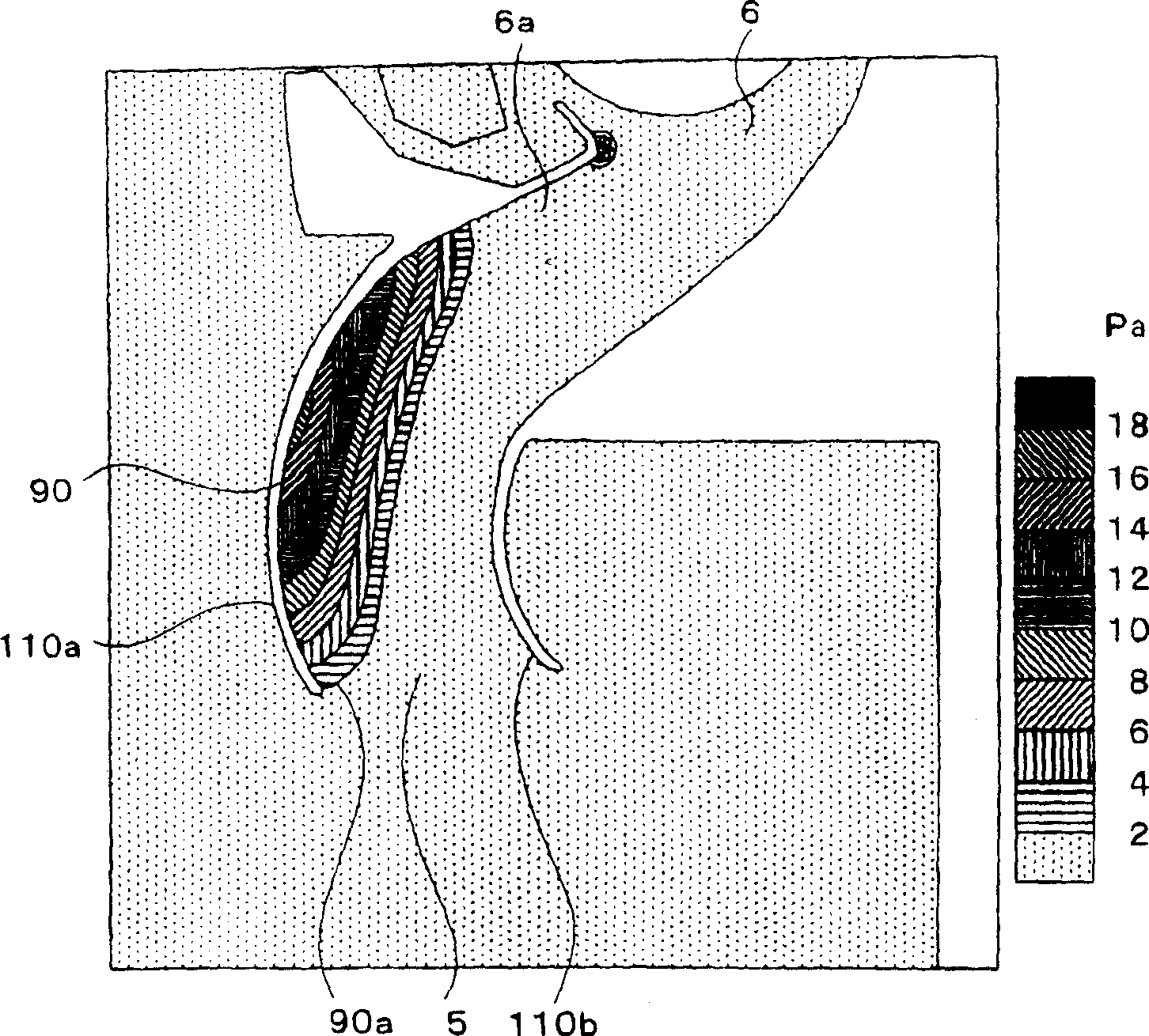
The present invention relates to an air conditioner. In a frontward direction relative to a front guide (6a) that guides conditioned air in a frontward-downward direction within a blowing passage (6), wind deflectors 110a and 110b are provided. When the conditioned air is sent out through the blowout port (5) in a straight downward direction or a rearward-downward direction, the wind deflectors 110a and 110b are so arranged that the static pressure distribution near them has a high static pressure part (90) where the static pressure is higher than in the front guide (6a) and that the isobars (90a) of the high static pressure part (90) run along the flow direction of the conditioned air flowing while facing the wind deflectors 110a and 110b.
Description
technical field The present invention relates to an air conditioner which regulates the air sucked into a cabinet and sends the air out to the room. Background technique Fig. 47 is a side sectional view showing an indoor unit of a conventional air conditioner disclosed in Japanese Patent Application Publication No. 2002-266437. The indoor unit 1 of the air conditioner is generally disposed at a position higher than the height of a user, and a main body is held by a casing 2 . The casing 2 is provided with claws (not shown) on the rear side, and the claws cooperate with a mounting plate (not shown) installed on the indoor side wall W1 to support the casing 2 . On the casing 2, a front panel 3 having a suction port 4 provided on the front side and the front side is detachably attached. A substantially rectangular air outlet 5 extending in the width direction of the indoor unit 1 is formed in a gap between the lower end of the front panel 3 and the lower end of the cabinet 2...
Claims
Login to View More Application Information
Patent Timeline
 Patent Type & AuthorityPatents(China)
IPC IPC(8): F24F13/06F24F1/00F24F13/15F24F13/20
CPCF24F2001/0048F24F1/0057
Inventor大塚雅生白市幸茂上原雄二铃木正一
OwnerSHARP KK