
Vacuum control system

A vacuum control and high vacuum technology, applied in the control/regulation system, fluid pressure control, non-electric variable control and other directions, can solve the problems of vacuum exhaust system 1 failure, oil seal medium splashing, vacuum degree limitation, etc. Ineffective effect

Inactive Publication Date: 2009-03-11
DELTA ELECTRONICS INC
View PDF6 Cites 0 Cited by
  • Summary
  • Abstract
  • Description
  • Claims
  • Application Information

AI Technical Summary

Problems solved by technology

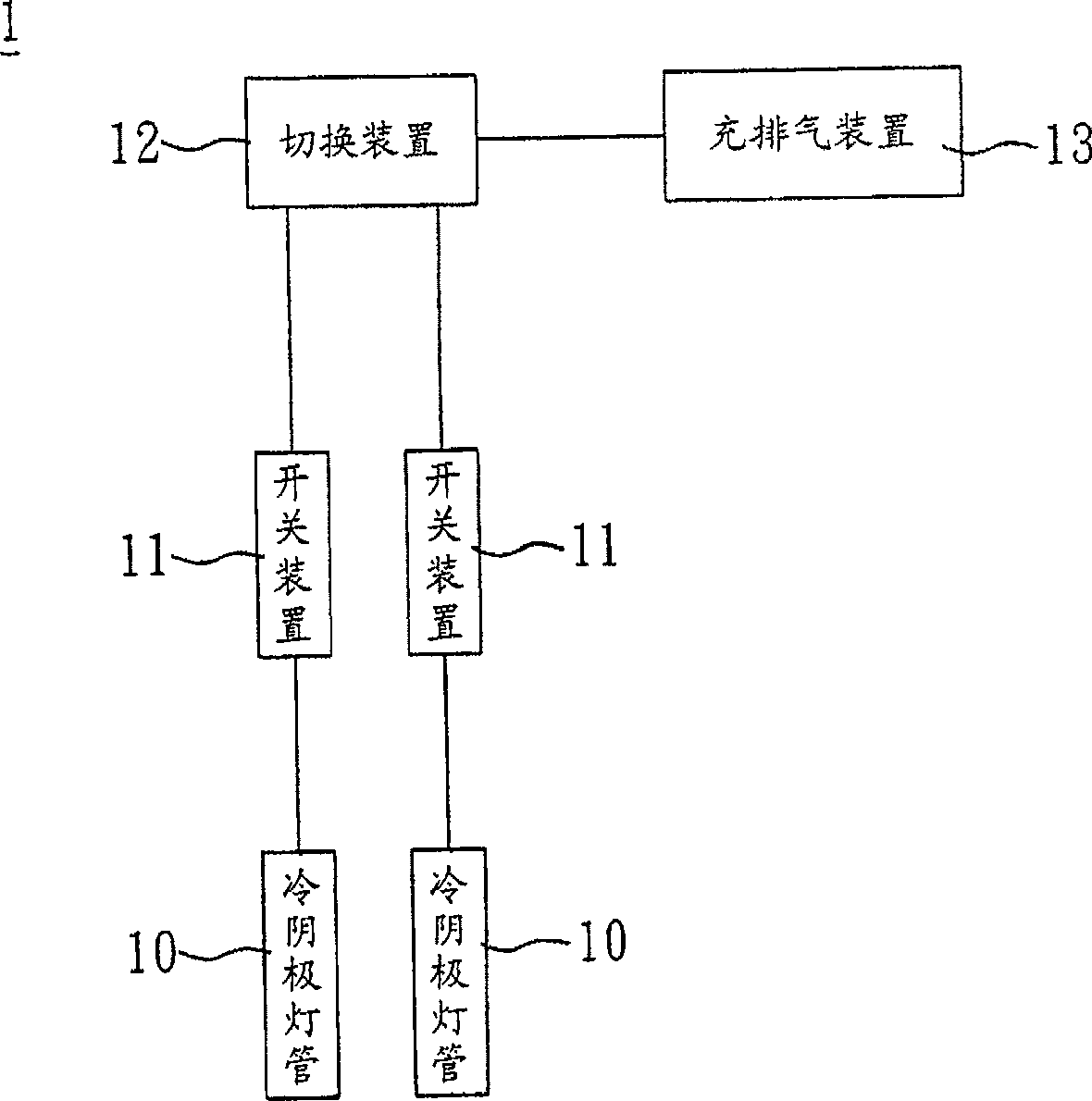
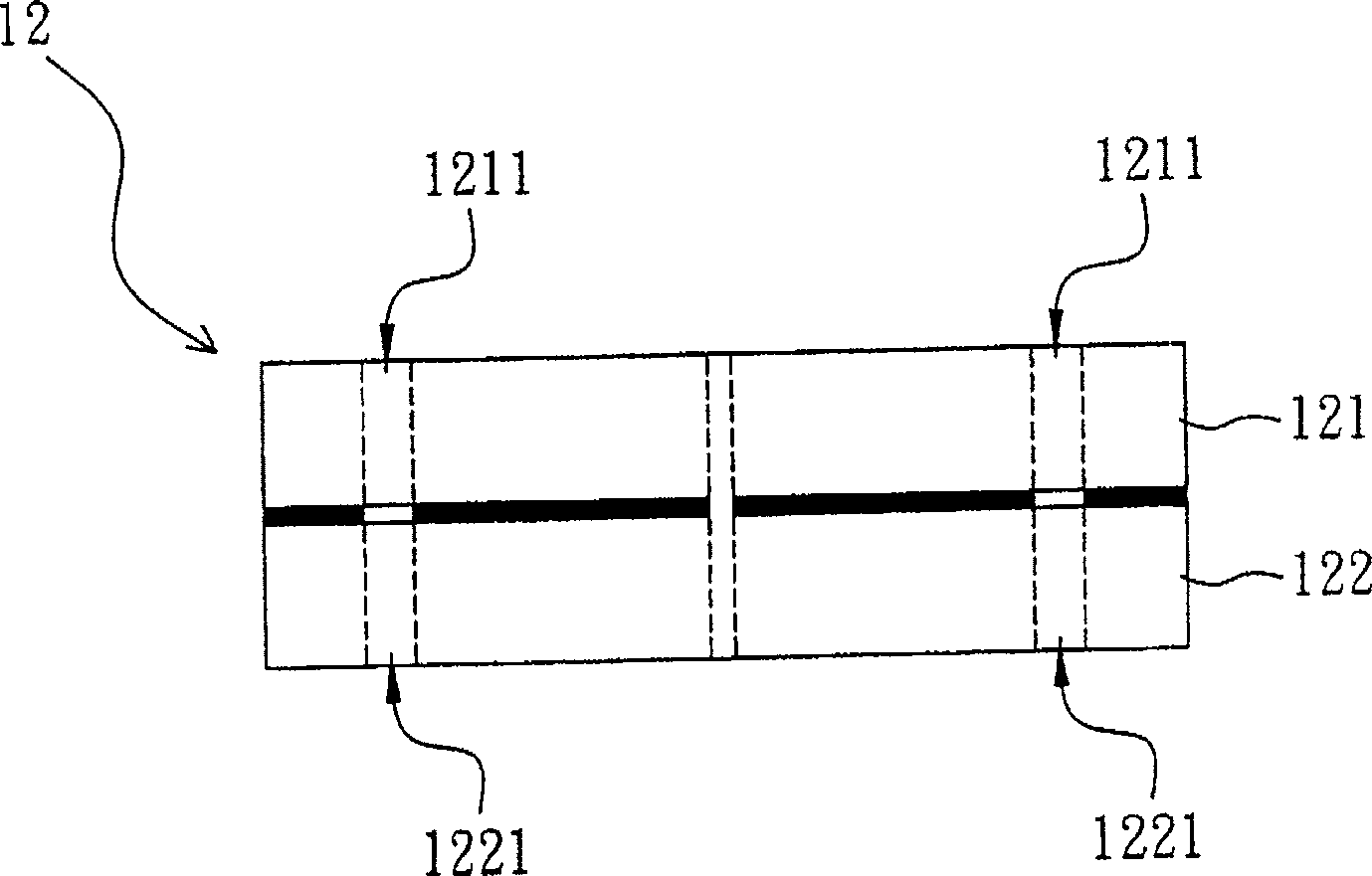
Wherein the first rotating unit 121 includes a plurality of first through holes 1211, the second rotating unit 122 includes a plurality of second through holes 1221, and the first through holes 1211 are respectively connected to the switching device 11, the charging and exhausting device 13 is connected to one of the second through holes 1221, so the cold cathode lamp tube 10 to be pumped is switched and selected through the relative communication between the first through hole 1211 and the second through hole 1221. However, due to the first rotation The interface between the unit 121 and the second rotating unit 122 is sealed with oil, so the degree of vacuum is limited, and since the charging and exhausting device 13 passes through the switching device 12 to carry out the pumping step, in order to achieve the purpose of increasing the vacuum degree, the switching device 12 It is easy to cause the oil seal medium in it to splash out due to excessive pressure, and the vacuum exhaust system 1 will fail

Method used


Image

  • Vacuum control system
  • Vacuum control system
  • Vacuum control system

Examples


Embodiment Construction

[0040] Hereinafter, a vacuum control system according to a preferred embodiment of the present invention will be described with reference to the related drawings, wherein the same components will be described with the same reference numerals.

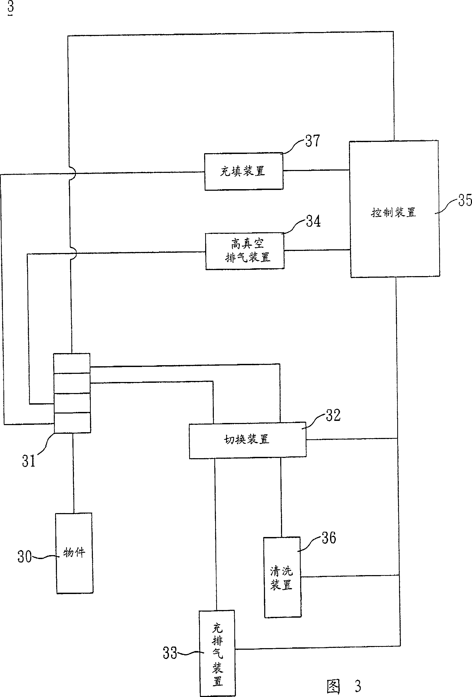
[0041] Referring to Fig. 3, a vacuum control system 3 according to a preferred embodiment of the present invention includes a switching device 31, a switching device 32, a charging and exhausting device 33, a high vacuum exhausting device 34 and a control device 35 .

[0042] The switch device 31 corresponds to an object 30 to be evacuated. In this embodiment, the object 30 may be a cold cathode lamp.

[0043] The switch device 32 is connected with the switch device 31, the inflation and exhaust device 33 is connected with the switch device 32, and the high vacuum exhaust device 34 is directly connected with the switch device 31. In this embodiment, the device 31 , 32 , 33 , and 34 can be connected by at least one pipeline respectively...


PUM


Abstract

A vacuum control system includes a switch device, a switching device, a charge and discharge device, a high vacuum discharge device and a control device, in which, said switching device is connected with the switch device, said charge and discharge device is connected with the switching device, said high vacuum discharge device is connected with the switch device, said control device is connected with the switch device, the switching device, the charge and discharge device and the high vacuum discharge device separately.

Description

technical field [0001] The invention relates to a vacuum control system, in particular to a vacuum control system with high vacuum efficiency. Background technique [0002] The vacuum exhaust system plays an important role in providing a vacuum environment in the manufacturing process technology of high-tech industries. For example, the vacuum exhaust system needs to be applied in the main manufacturing processes of the semiconductor or optoelectronic industries. However, with the quality of products With the increase of demand, the requirements for vacuum degree in the product manufacturing process are also getting higher and higher. Therefore, the structure and design of the vacuum exhaust system have become important factors. [0003] The following is an example of the vacuum exhaust system for cold cathode lamps used in the optoelectronic industry, such as figure 1 As shown, the traditional vacuum exhaust system 1 includes a plurality of switching devices 11, a switchin...

Claims


Application Information

Patent Timeline
Patent Type & Authority Patents(China)
IPC IPC(8): H01L21/203C23C14/24F04B37/14G05D16/00
Inventor 林世贤洪荣宗张正宜黄志强
Owner DELTA ELECTRONICS INC
Learn More