Image forming apparatus

An imaging device and imaging technology, applied in printing devices, transportation and packaging, electrography, etc., can solve the problem of increasing the width of the post-processor

Active Publication Date: 2009-03-25
NISCA KK
View PDF10 Cites 0 Cited by
  • Summary
  • Abstract
  • Description
  • Claims
  • Application Information

AI Technical Summary

Problems solved by technology

[0013] That is, the length of the paper generally used is different in the direction of the larger size and the direction of the smaller size. If the direction of the larger size of the largest size paper, the image forming and post-processing and the scanning direction of the manuscript are arranged side by side in the same direction, Then there is the following disadvantage, that is, in the paper finisher, the functional parts such as staple paper, the driver for driving and controlling it, and the driver for conveying the paper, such as the conveying roller, protrude from the left and right, and the width of the finisher increases.
[0014] In particular, there is the disadvantage that the functional parts of the post-processor must require a mechanism that can be removed from the outside of the processor for replacement of consumables and maintenance of malfunctions. Components stand out especially on the outside

Method used


Image

  • Image forming apparatus
  • Image forming apparatus
  • Image forming apparatus

Examples


Embodiment Construction

[0034] Hereinafter, the paper conveying device and the image reading device of the present invention will be described in detail based on the drawings.

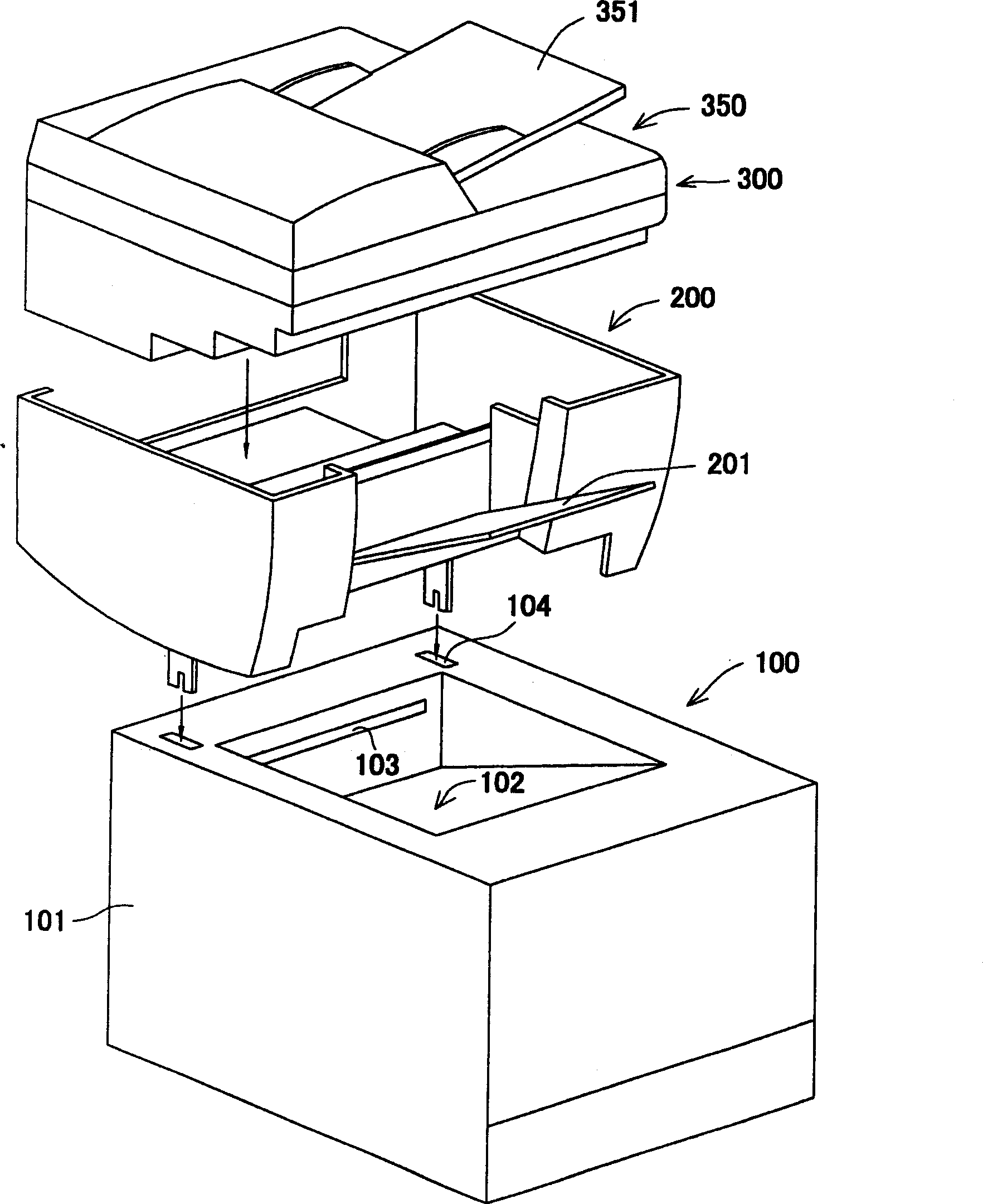
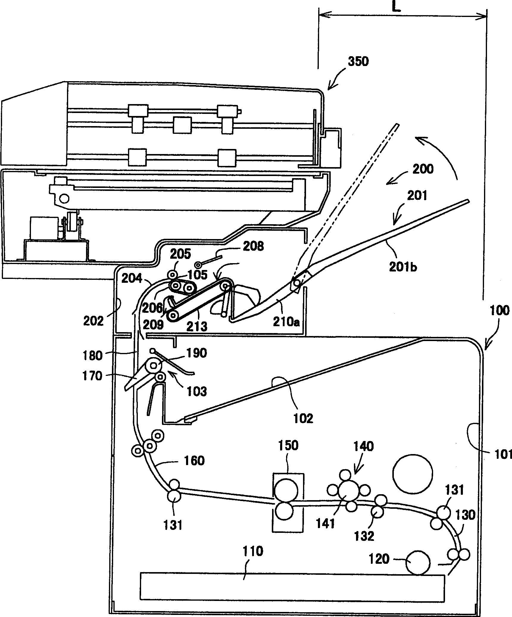
[0035] figure 1 To show a perspective view of an embodiment of the present invention, figure 2 It is a longitudinal sectional view. This figure shows a situation where the imaging unit 100, the paper post-processing unit 200 and the image reading unit 300 are housed in separate housings, and depending on the purpose used, for example, in a computer (not shown in the figure). Shown) is connected and used as a printer only through the imaging unit 100. When post-processing functions such as stapling (paper binding) are added to it, the paper post-processing unit 200 and the imaging unit 100 are combined to form the device In addition, when the image reading module is used for copying and other purposes, the image reading module 300 is combined to form a device, and in this way, separate modules are formed.

[0036] The image for...


PUM


Abstract

Respective sheet ejection stackers 102 and 201 are arranged so that the feeding direction of a sheet ejected from the image forming unit 100 may become the same as that of a sheet ejected from the sheet post-processing unit 200, and the sheet (original) scanning direction of the image reading unit 300 is made nearly perpendicular to the feeding direction of both sheets.

Description

Technical field [0001] The present invention relates to imaging devices such as copiers, printers, fax machines, etc. The present invention relates to the following imaging devices, which include an imaging assembly that prints an image on a paper medium; an image reading assembly that passes through The photoelectric conversion mechanism reads the original image of the manuscript, etc.; the paper post-processing component, which binds, perforates, or seals the printed paper from the imaging component. The present invention relates to the following imaging The imaging device is provided with a paper post-processing component above the imaging component, and in addition, an image reading component is provided above the paper post-processing component. Background technique [0002] Generally, such an image forming apparatus is known as a copying machine or a facsimile machine. The copying machine uses an image forming unit to copy a manuscript that has been read by an image reading...

Claims


Application Information

Patent Timeline
Patent Type & Authority Patents(China)
IPC IPC(8): B41J13/10B65H37/04G03G15/00
CPCG03G15/6573
Inventor 齐藤隆
Owner NISCA KK
Why Eureka
Try Eureka