
Sun shelter

a technology for sun lounges and shelters, applied in the field of sun lounges, can solve the problems of limited degree of adjustment, more people using the sun lounge, and more people being forced to receive more sun loungers,

Pending Publication Date: 2022-08-25
CLARKE RODNEY CHRISTOPHER
View PDF0 Cites 0 Cited by
  • Summary
  • Abstract
  • Description
  • Claims
  • Application Information

AI Technical Summary

Benefits of technology

The invention is a new sun shelter that allows people to choose how much sun they want. It is made up of a shine canopy that can be extended or retracted to change the amount of sun coverage. The support structure is strong and sturdy, making sure the canopy is always stable. Overall, this new sun shelter provides more flexibility and customization for sun lounge users.

Problems solved by technology

Importantly, the position of the sun in the sky and the height and size of the canopy of a sun shelter significantly affects how much useful shade falls directly beneath the canopy for the benefit of a person occupying a sun lounge below the canopy, and how much additional shade is projected to areas beyond directly beneath the canopy's perimeter and which is generally superfluous in terms of protecting a person using a sun lounge against exposure to ultraviolet radiation.
This commonly results in a person using the sun lounge being forced to receive more or less sun or shade than desired for extended periods throughout the day depending on their position relative to the sun and the center pole.
This occurs because, where two sun lounges share a single umbrella positioned between them, this uneven distribution of shade often results in the sun lounge on the side nearest the sun being exposed to more direct and reflected sunlight than the other.
This problem is more pronounced during morning and afternoon when the sun is lower in the sky, whereby the sun's rays can readily penetrate diagonally beneath the elevated canopy.
This limited degree of adjustability is generally unsatisfactory because the canopy can become more oblique in its orientation relative to the sun, thereby producing a smaller amount of narrow shade, while significantly increasing resistance to wind load.
This pole height has an associated negative consequence in that the greater the elevation of the canopy above the ground, the greater the scope for more sun light to penetrate underneath the umbrella.
Many of the limitations discussed above also restrict the suitability of side-mounted umbrellas (for example, wall-mounted or cantilevered umbrellas that do not have a central pole) and often result in unsatisfactory shade performance in situations where mobility and limited space are a consideration.
The close proximity of adjacent sun lounges in the settings described above where available space is limited, exacerbates the aforementioned problems associated with the height of conventional umbrellas and the necessarily large relative surface area of their canopies, which together cause shade to be projected over a significantly greater space than that occupied by the intended sun lounge or lounges they overlie.
Further, in such circumstances there is little or no scope to reposition sun lounges that are arranged in close proximity to one another or to adjust the placement of the umbrella to negate the shifting of shade due to the sun's movement across the sky.
As such, one or two guests sharing a single umbrella typically have little or no control over the amount of sun light or shade they receive, such that parts of their body may often be exposed or covered contrary to the user's preferences.
These limitations can combine to reduce the enjoyment of hotel, resort and cruise ship guests and detrimentally affect poolside food and beverage revenues.
This is not a simple exercise and likely requires a basic level of skill to properly fit the canopy to a new position and thus the user does not have a quick and convenient way of adjusting shade levels.
The extent of adjustment is also limited by the canopy being formed to have a single, generally square shape.
Moreover, the generally convex shape of a conventional umbrella canopy when in an opened state, is also prone to poor wind resistance when experiencing an updraft, often causing an umbrella to be lifted and propelled in the direction of the wind and presenting a danger to anyone in its path.
Alternatively, the base can be arranged to cooperate with a separate weight so that until the separate weight is applied to the base, the base does not necessarily meet the requirement to support the sun shelter in a stable manner.
Alternatively, the separate weight might only be required when excessive wind conditions are such as to potentially make the sun shelter unstable.
This would be in contrast to a collection of outdoor furnishings assembled from a variety of diverse, unrelated sources which will adversely result in an eclectic, disjointed mix of decor that is less than pleasing to the eye.
Accordingly, the pairing of a free-standing adjustable sun shelter with a pre-existing deck chair or sun lounge where each separate item may be of a contrasting physical appearance, will be unsatisfactory for many hotel, resort and cruise ship operators seeking to provide outdoor furnishings of a consistent quality and visual appearance.
Further, because the sight of shade canopies above sun lounges in some environments may be considered unattractive, for example detracting from the ambience of a swimming pool precinct, some forms of this embodiment of the invention provide for adjustment to retract the shade canopy and the support structure from overlying the sun lounge.
However, with rearward folding movement reducing the overall length of the side frame members, the folded side frame members of the shade canopy can rotate or collapse with the support posts directly into the storage cavities, receptacles or compartments of the sun lounge.

Method used


Image

  • Sun shelter
  • Sun shelter
  • Sun shelter

Examples


Embodiment Construction

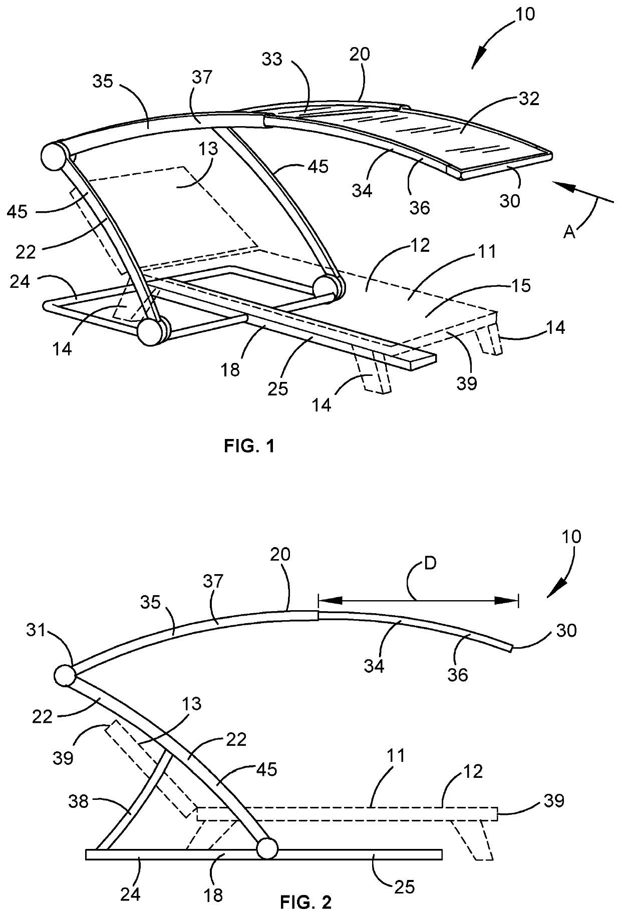
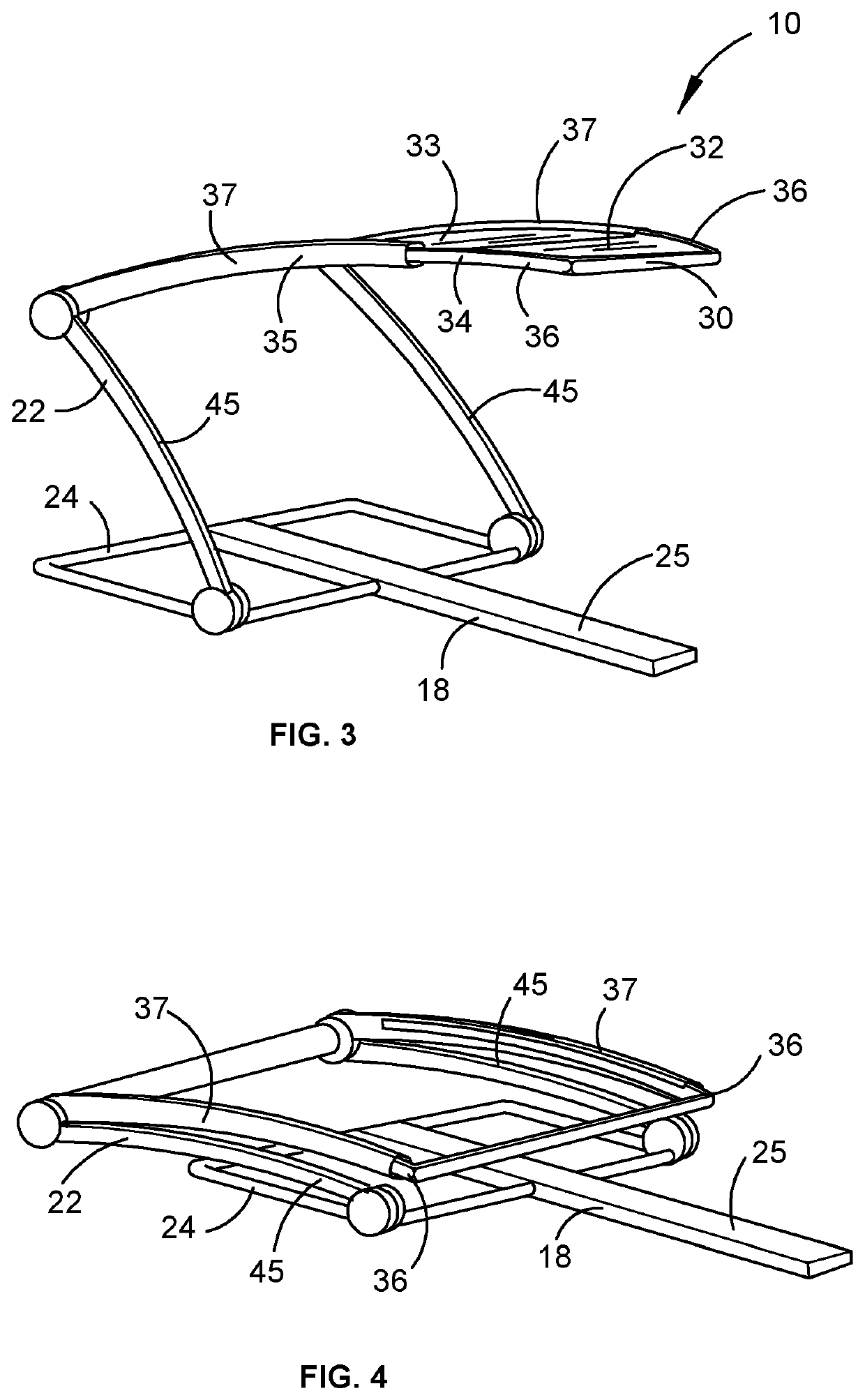
[0153]FIG. 1 illustrates one form of personal sun shelter 10 according to the embodiment. The sun shelter 10 is shown in place relative to a sun lounge 11 that is shown in broken line. The sun lounge 11 takes a standard form in which it includes a flat bed section 12 and an inclined head section 13. Legs 14 elevate the sun lounge 11 above the ground. The upper surface 15 of the bed section 12 and the head section 13 is a reclining surface for a person to sit or recline on.

[0154]The sun shelter 10 is customised for use with the single sun lounge 11. The shelter 10 is therefore constructed for the provision of shade substantially just to the sun lounge 11 and as will become apparent from the discussion that follows, more accurately cast or projected shade can be provided by sun shelters according to the embodiment as compared to the traditional form of umbrellas discussed above.

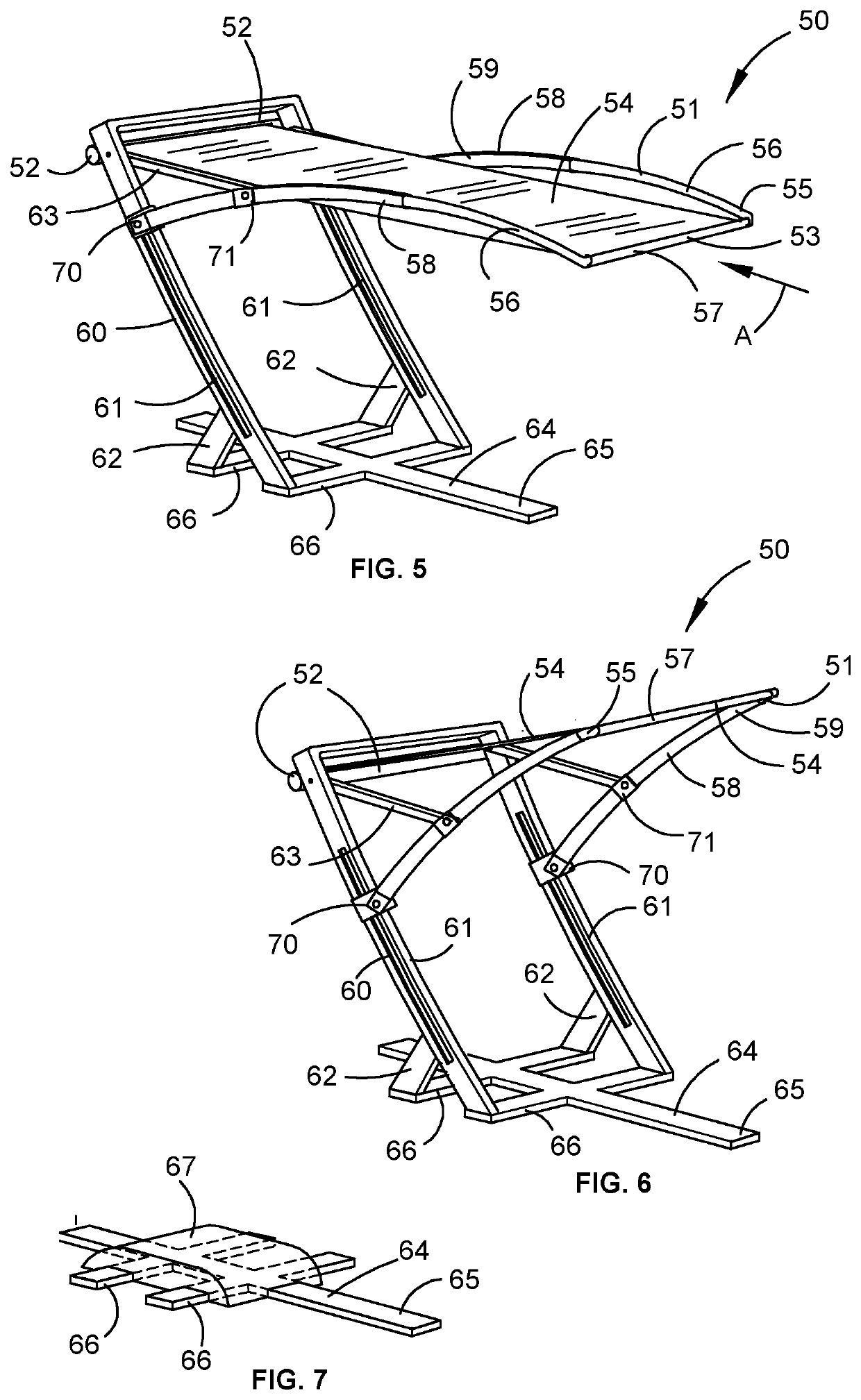
[0155]The sun shelter 10 includes a base 18, a shade canopy 20 and a support structure 22. The base 18 is fo...


PUM


Abstract

An adjustable personal sun shelter to overlie a free-standing or integrated sun lounge or deck chair of the kind commonly occupied by a user while sunbathing beside a swimming pool. The adjustable personal sun shelter includes a base and a support structure that suspends a shade canopy in a cantilevered state above an underlying sun lounge at an optimal height to project shade over the sun lounge. The shade canopy is adjustable by a user to vary the amount of sunlight or shade received when occupying the underlying sun lounge. The shade canopy is adjustable by an extendable central member or by two or more parallel extendable side members, to which shade material is fastened. The shade canopy has a moveable leading end and a fixed trailing end. In the operational condition of the sun shelter, the length of the shade canopy can be increased by extending the leading end of the shade canopy relative to the trailing end, or the length can be decreased by retracted the leading end.

Description

CROSS-REFERENCE TO RELATED APPLICATIONS[0001]This application is the U.S. National Phase under 35. U.S.C. § 371 of International Application PCT / AU2020 / 050764, filed Jul. 27, 2020, which claims priority to Australian Application No. 2019902696, filed Jul. 29, 2019, and to Australian Application No. 2019904312, filed Nov. 15, 2019. The disclosures of the above described applications are hereby incorporated by reference in their entirety and made a part of this specification.BACKGROUNDField[0002]The present invention relates to a sun shelter for the application of shade to outdoor lounges and chairs, such as are typically used on sun decks, or about swimming pools or on beaches. It will be convenient to describe the invention in relation to its particular use with sun lounges supplied for guests of hotels, resorts and cruise ships, although it needs to be appreciated that the invention could be used with other outdoor reclining or seating furniture, such as deck chairs.Related Art[000...

Claims


Application Information

Patent Timeline
IPC IPC(8): A47C7/66A45B11/00A45B23/00A47C1/14
CPCA47C7/666A45B11/00A45B23/00A47C1/143A45B2023/0006A45B2023/0093A45B2200/1009A47C7/66A47C1/146A45B2011/005
Inventor CLARKE, RODNEY CHRISTOPHER
Owner CLARKE RODNEY CHRISTOPHER
Learn More