Power management method for built-in camera

A power management and camera technology, applied in the direction of data processing power supply, etc., can solve problems such as unfriendliness, power consumption, system power consumption increase, etc., to achieve the effect of enhancing user experience and enhancing usability

Inactive Publication Date: 2009-03-25
LENOVO (BEIJING) LTD
View PDF4 Cites 1 Cited by
  • Summary
  • Abstract
  • Description
  • Claims
  • Application Information

AI Technical Summary

Problems solved by technology

The built-in camera will increase the power consumption of the system. There are two main reasons: First, most of the built-in cameras are USB (1.1 / 2.0) interfaces, which consume power even when the camera is not working.
Second, because after the system inserts the USB device, the CPU will leave the low power consumption state; therefore, after the notebook has a built-in camera, as long as the notebook is turned on, the USB device will always exist from the perspective of the system. In this case, the CPU will never enters a low-power state, resulting in an increase in power consumption
The built-in camera needs to be powered from the USB port of the notebook, so there is no way to control its own power switch according to the needs. For example, after the camera is built in the power-on state, the user cannot reduce the power consumption of the entire system by plugging and unplugging the camera.
Using hardware to realize automatic camera control will increase the cost of the notebook, and will affect the hardware design of the entire notebook, making it very difficult to implement
It is unfriendly in terms of user experience, for example: if the user forgets to turn on the power of the camera when starting up, the system will report an error when running the camera-related software; if the firmware (Firmware) turns on the camera by default when starting up, but the user does not use the camera-related software, which will increase the power consumption of the system and affect the battery life

Method used


Image

  • Power management method for built-in camera
  • Power management method for built-in camera
  • Power management method for built-in camera

Examples


no. 1 example

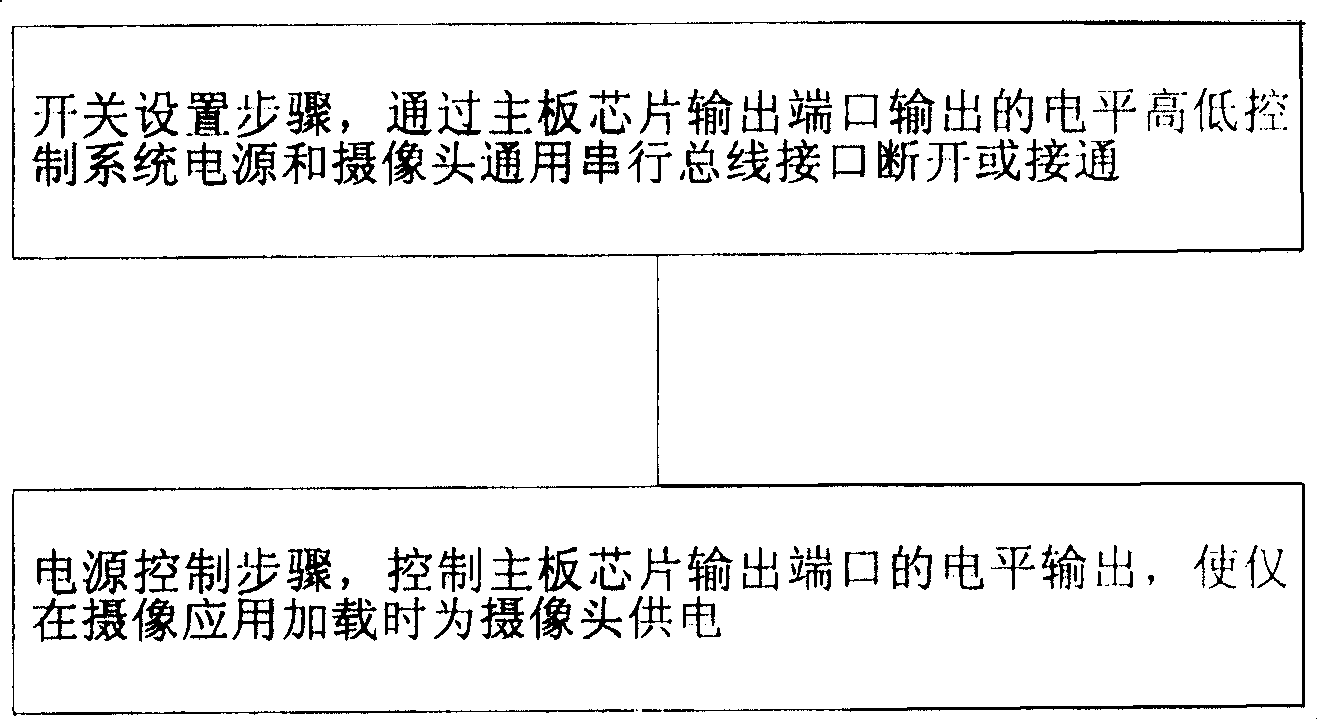
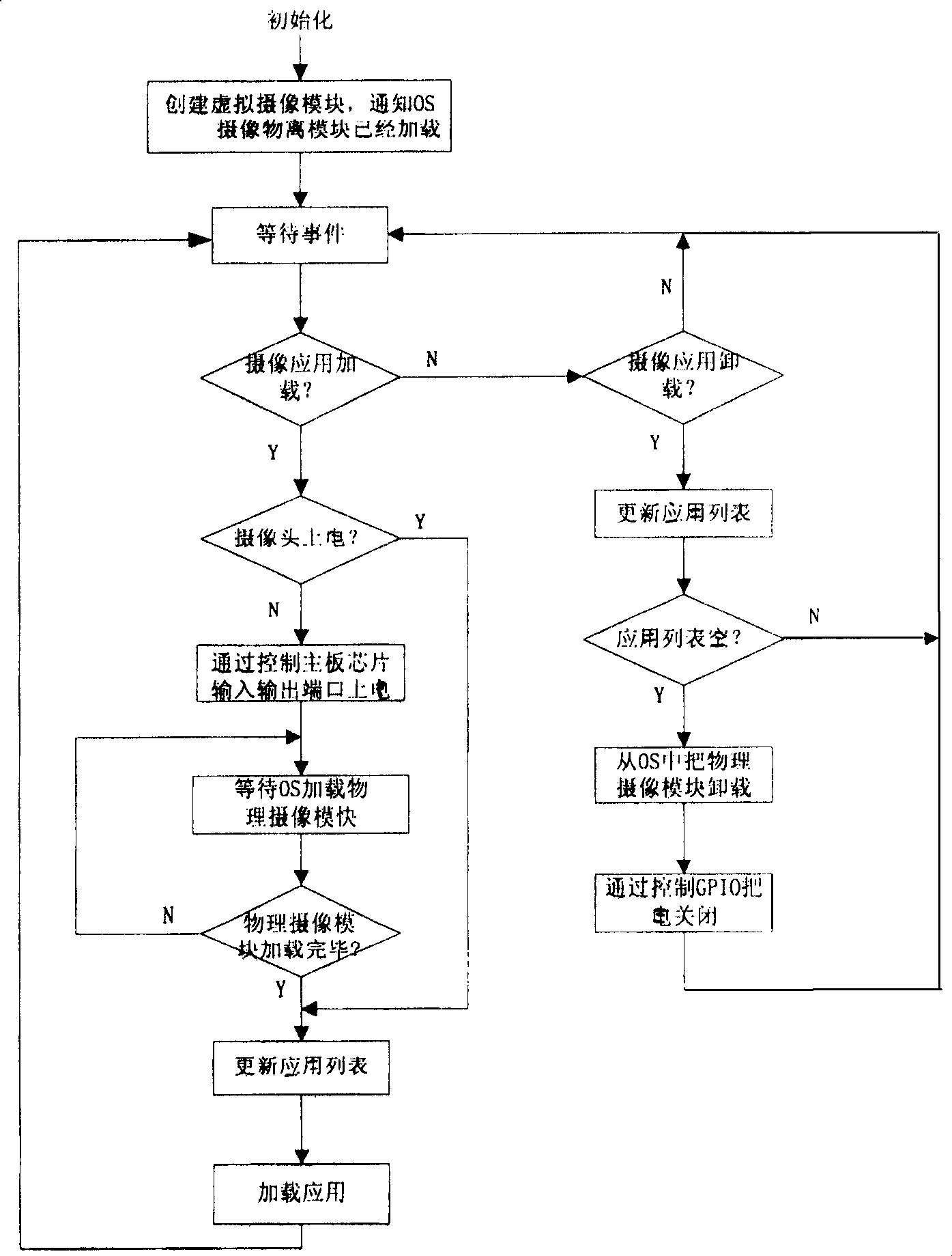
[0034] Please refer to figure 2 The first embodiment of the shown power control step includes:

[0035] 1) Create a virtual camera module (Camera Shadow) to notify the operating system that the virtual camera has been loaded (as long as the Camera Shadow is loaded, the operating system will think that the camera exists, and the virtual camera module will be loaded when the system starts. As long as the virtual module is loaded, the operating system will It will be considered that there is a camera device, so that the operating system will not load the camera module because the camera hardware is not powered on, so that it will not cause difficulties for the user to find the camera application), the virtual camera module provides the calling interface of the camera application, If the operating system is XP, Camera Shadow provides a Component Object Model (COM) interface for camera applications;

[0036] 2) Wait for system events to determine whether the camera application is...


PUM


Abstract

The invention discloses a method for managing power of built-in camera which comprises steps of: switch setting step, controlling the on and off of system power and camera general serial bus interface via the high / low level output from main board chip; power control step, controlling the level output from the main board chip output interface for providing power when loading camera application. The invention modifies the hardware circuit of the built-in camera by employing GPIO to control power of USB plugging components in the USB interface connected with the camera, and realizing the control of camera power via controlling GPIO, thereby prolonging cell endurance.

Description

technical field [0001] The invention relates to a power management method of a universal serial bus device, in particular to a power management method of a built-in camera. Background technique [0002] With the improvement of the integration level of USB (Universal Serial Bus, universal serial bus) interface passive response universal serial bus devices, for example, taking a camera as an example, more and more notebook computers provide a built-in camera function. The built-in camera will increase the power consumption of the system. There are two main reasons: First, most of the built-in cameras are USB (1.1 / 2.0) interfaces, which consume power even when the camera is not working. Second, because after the system inserts the USB device, the CPU will leave the low power consumption state; therefore, after the notebook has a built-in camera, as long as the notebook is turned on, the USB device will always exist from the perspective of the system, and in this case the CPU wi...

Claims


Application Information

Patent Timeline
Patent Type & Authority Patents(China)
IPC IPC(8): G06F1/32
Inventor 刘旭国程孝仁袁康
Owner LENOVO (BEIJING) LTD
Why Eureka
Try Eureka