Electric leg-separating mechanism

A technology of electric leg separation and photoelectric switch, which is applied in the fields of medical science, surgery, operating table, etc., can solve the problems of position deviation of travel switch and wear of travel switch, so as to avoid wear, high sensitivity and suitable for long-term application Effect

Active Publication Date: 2009-04-01
TAICANG KANGHUI TECH DEV
View PDF10 Cites 0 Cited by
  • Summary
  • Abstract
  • Description
  • Claims
  • Application Information

AI Technical Summary

Problems solved by technology

However, since the limit switch is directly touched during the working process, the limit switch will be worn out after long-term use, which may easily cause deviations in the action position of the limit switch.

Method used


Image

  • Electric leg-separating mechanism
  • Electric leg-separating mechanism
  • Electric leg-separating mechanism

Examples


Embodiment Construction

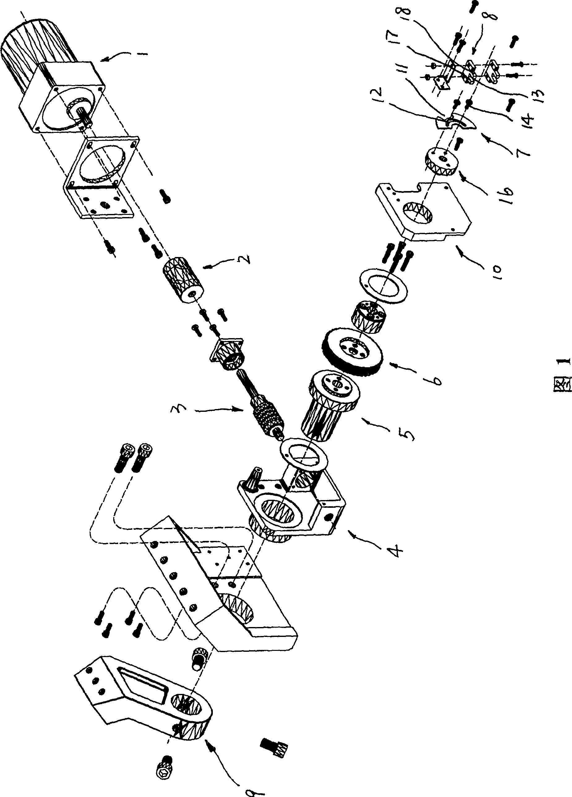
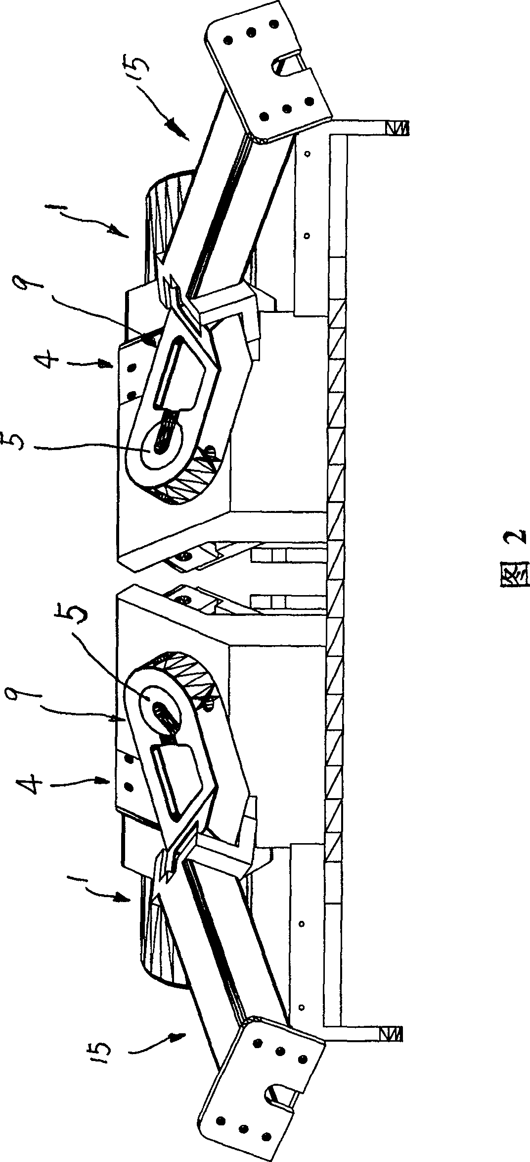
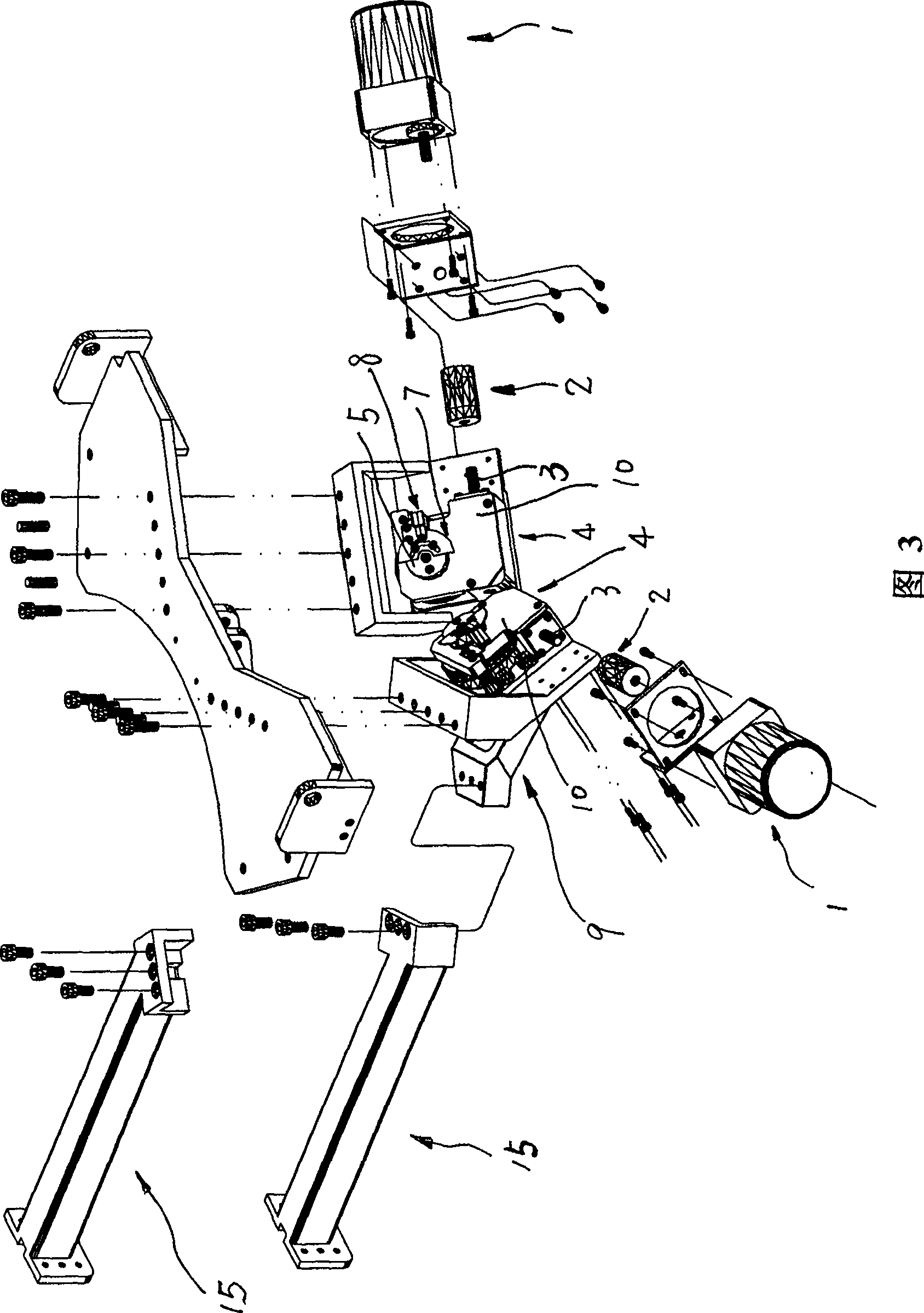
[0018] See Attached Figure 1—Attachment Figure 6 , an electric leg splitting mechanism, including a motor 1, a worm 3 connected to the output shaft of the motor 1, a worm wheel 6 meshed with the worm 3, and a pendulum connected to the worm wheel 6 in transmission. Block 9, the leg rod 15 fixedly connected with the pendulum block 9, it also includes a photoelectric switch 8, the photoelectric switch 8 has a groove 13, and one side of the groove 13 is for optical signal emission Contact 17, the other side of the groove 13 is an optical signal receiving contact 18, the groove 13 of the photoelectric switch 8 is inserted with a light blocking sheet 7, and the light blocking sheet 7 is provided with The light-transmitting gap 11 , the photoelectric switch 8 is electrically connected to the input end of the programmable controller 19 , and the output end of the programmable controller 19 is electrically connected to the motor 1 .

[0019] Referring to the accompanying drawing 5, t...


PUM


Abstract

The present invention relates to an electric legs-separating mechanism. Said mechanism includes the following portions: motor, worm and worm gear, swing block, leg bars, photoelectric switch, optical signal transmitting contact head, optical signal receiving contact head and programmable controller. Said invention also provides their connection mode and working principle of said legs-separating mechanism.

Description

technical field [0001] The invention relates to an electric leg splitting mechanism, which is usually used to control the opening or closing action of the leg plate of a medical delivery bed. Background technique [0002] The existing electric leg splitting mechanism includes a motor, a worm connected to the output shaft of the motor, a worm wheel meshed with the worm, a pendulum connected to the worm gear, a leg rod fixedly connected to the pendulum, and the legs of the delivery bed. The plate is set on the leg bar, and a mechanical travel switch is set between the power supply and the power input end of the motor, that is, when the pendulum drives the leg bar to move to realize the opening or closing of the leg plate, through the mechanical structure Movement to touch the limit switch to control the working state of the motor. However, since the travel switch is directly touched during the working process, the travel switch will be worn after long-term use, which will eas...

Claims


Application Information

Patent Timeline
Patent Type & Authority Patents(China)
IPC IPC(8): A61G13/10A61G13/00
Inventor 陈利忠
Owner TAICANG KANGHUI TECH DEV
Why Eureka
Try Eureka