

Satellite acceptor shell and forming method
A receiver and molding method technology, which is applied in the field of satellite receivers, can solve the problems of O-ring deformation, rainwater infiltration, failure to achieve waterproof function, etc.
- Summary
- Abstract
- Description
- Claims
- Application Information
AI Technical Summary
Problems solved by technology
Method used
Image

Examples
Embodiment Construction
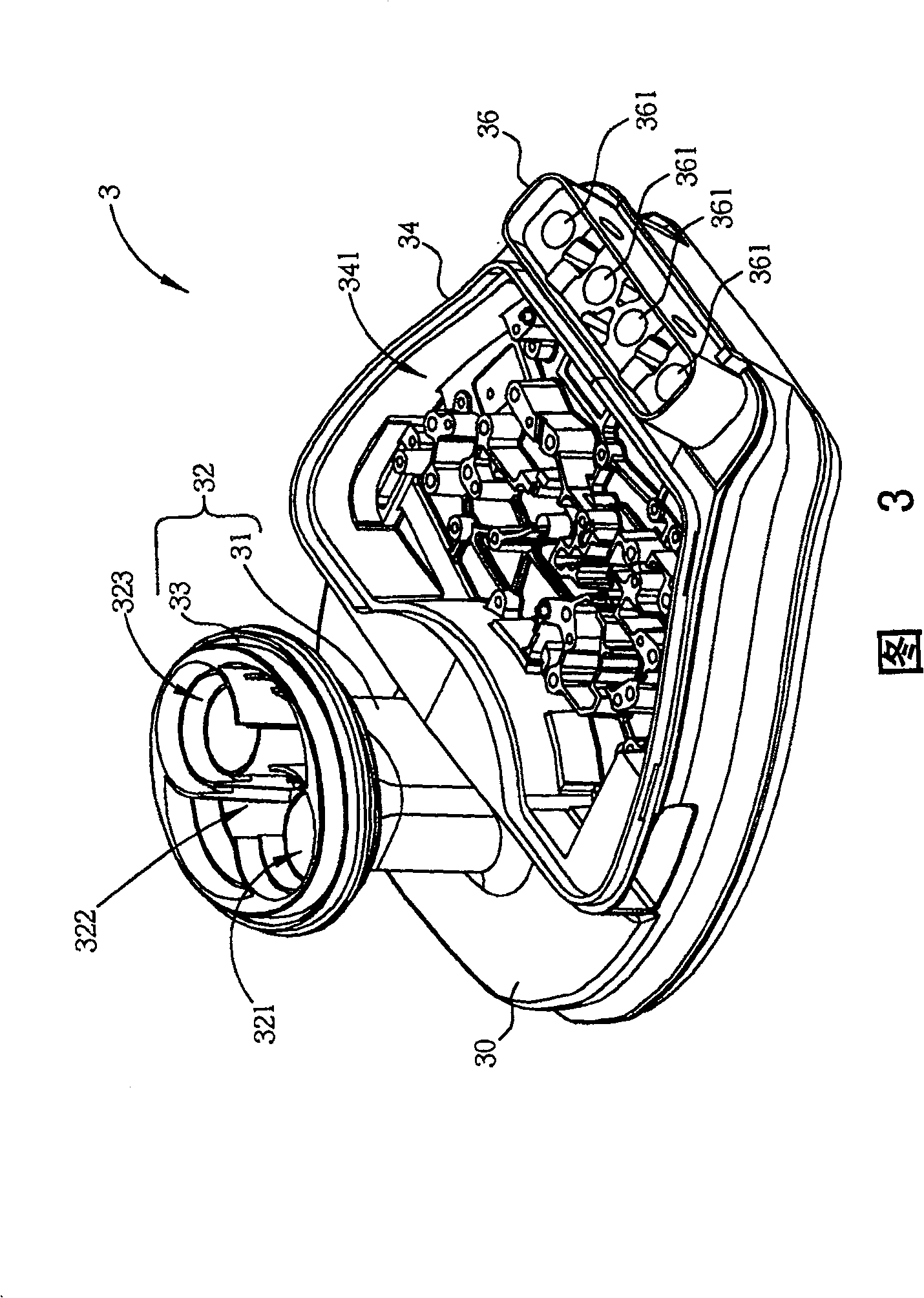
[0014] Please refer to FIG. 3; FIG. 3 is a schematic diagram of a satellite receiver 3 of the present invention. The satellite receiver 3 includes a main body 30 , a signal feed-in portion 32 , a first circuit board accommodating portion 34 and a signal output portion 36 . The signal feeding part 32 includes a cylinder 31 , an opening 33 and a plurality of signal receiving ends 321 , 322 , 323 for receiving satellite signals. The first circuit board accommodating portion 34 includes a first groove 341 for accommodating a circuit board. The signal output unit 36 includes a plurality of signal output terminals 361 . The satellite receiver 3 of the present invention is integrally formed without assembling gaps, so that the assembling gaps can avoid affecting the quality of receiving satellite signals and avoid rainwater penetration.
[0015] Please refer to FIG. 4 to FIG. 6; FIG. 4 to FIG. 6 are a side view, a top view and a bottom view of the satellite receiver 3, respective...
PUM
 Abstract
Description
Claims
Application Information