
Electric power installation of artificial tornado, and generating method

A technology of artificial tornado and power generation device, applied in wind power generation, wind power generator components, wind power generators consistent with the wind direction, etc., can solve the problems of not reaching the strong airflow of tornado, not forming tornado effect, and insufficient pipeline length, etc. To achieve the effect of short construction period, reduce greenhouse gas emissions, and maintain a long time

Inactive Publication Date: 2009-04-29
梁和平
View PDF10 Cites 2 Cited by
  • Summary
  • Abstract
  • Description
  • Claims
  • Application Information

AI Technical Summary

Problems solved by technology

Its shortcomings are as follows: first, the motive force is not ideal, such as the instability of natural wind, heating air or electric blower need to consume other energy; second, when the generated cyclone rises in the ordinary pipeline or in the local space, due to the surrounding gas Due to the blocking effect of the pipe wall friction, the cyclone will gradually weaken, and the central negative pressure will decrease or even disappear, and the tornado effect cannot be formed; the third is that the length of the pipe is not long enough to reach the strong airflow similar to a tornado

Method used


Image

  • Electric power installation of artificial tornado, and generating method
  • Electric power installation of artificial tornado, and generating method
  • Electric power installation of artificial tornado, and generating method

Examples


Embodiment 1

[0039] Embodiment 1: Design and build a 10,000 kilowatt artificial tornado power station.

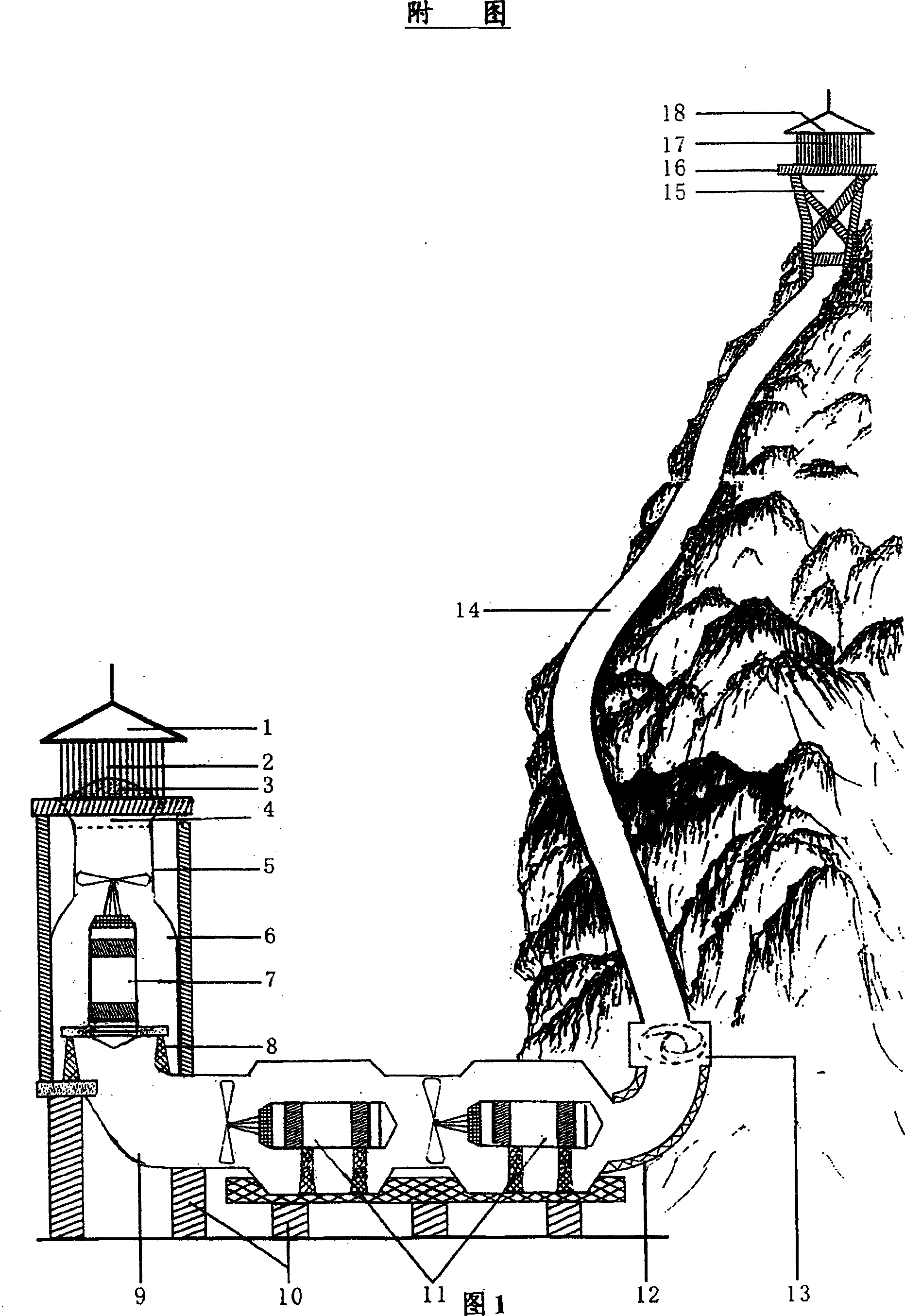
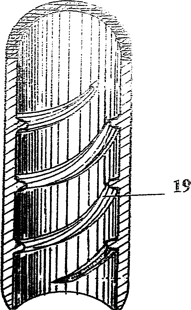
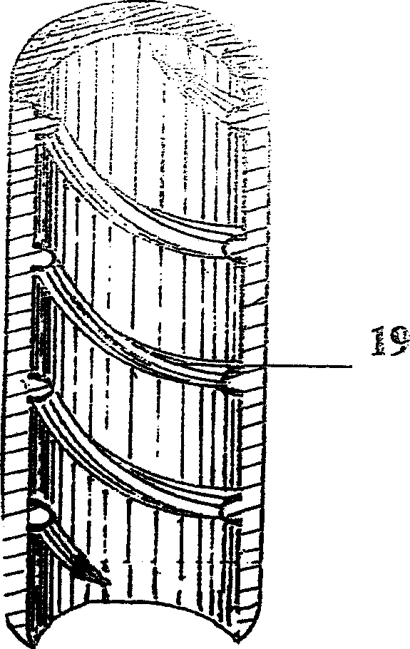
[0040] First, choose a steep mountain with a vertical height of more than 1,500 meters and a slope greater than 45° as the foundation for laying the spiral ridge pipeline 14, and explore the geology and lines, and design the construction blueprint. Simultaneously use plastics (such as PE) to make the spiral ridge pipeline 14 of length 9m, inner cavity diameter 3.5m, tube wall thickness is calculated by 2% of inner cavity diameter, is about 6cm, and the height of the spiral ridge 19 that protrudes into the lumen is by the lumen 10% of the diameter, about 35cm. It is laid obliquely at a slope of 45°, reaching a vertical height of 1500m, so that a gradient temperature difference of about 10°C can be obtained.

[0041] On the high part of the mountain, build a funnel-shaped exhaust bucket 15 with a diameter of 5.5m at the upper opening and 3.5m at the lower opening, the diameter of which i...

example 2

[0057] Example 2 Design and build a 100,000-kilowatt artificial tornado power plant

[0058] First, select a steep mountain with a vertical height of more than 2,000 meters and a slope greater than 45° as the foundation for laying the spiral ridge pipeline 14, explore the geology and lines, and design the construction blueprint. And use plastics (such as PE) to manufacture the spiral ridge pipe 14 with a length of 18m and an inner hollow diameter of 9.90m. The thickness of the tube wall is about 50 cm based on 5% of the inner hollow diameter, and the height of the spiral ridge 19 protruding into the lumen is about 100 cm based on 10%. Lay obliquely at a slope of 45° until reaching a vertical height of 2000m, so that a gradient temperature difference of about 13°C can be obtained.

[0059] At the height of the mountain, build a 15m-diameter upper opening and a 9.9-m inner hollow diameter at the lower opening (its diameter is consistent with the spiral ridge pipeline 14), a fun...


PUM


Abstract

An artificial cyclone generating device and its generating method are disclosed in the present invention, through guiding ascent airflow to form high speed cyclone, thus generates controllable cyclone and uses for generating. The device pipeline system is sequentially connected by air inlet window, gas filtering net, gas inlet funnel, propeller pipe, vertical motor cabin, airflow guiding pipe, airflow heating pipe, adjustable ventilating gate, spiral ridge pipeline, air outlet funnel and air outlet window according to the airflow inlet and outlet flow direction. A vertical generator and horizontal generator are arranged in the pipeline, spiral ridge extending with spiral type along the pipeline axial direction is arranged on the round inner wall of the spiral ridge pipeline. Through the spiral ridge pipeline laying, mounting along the steep mountain body, the spiral ridge makes the ascent airflow flowing in its pipe form rotary artificial cyclone, using the artificial cyclone to driving the generator arranged in the pipeline system to generate.

Description

[0001] Technical field [0002] The invention relates to a renewable energy power generation device and a power generation method thereof, in particular to an artificial tornado power generation device and a power generation method thereof. Background technique [0003] With the rapid development of modern science and technology and the continuous improvement of people's living standards, the energy consumption of industry and commerce and household appliances has increased sharply, and the world's energy is facing a state of tension. At present, the energy used by people mainly comes from coal, oil, natural gas, nuclear reactors and hydroelectric power. Most of these energy sources have limited resources and environmental pollution, and are far from meeting people's needs. In view of this, some people have been exploring and developing "green energy" for many years, such as solar energy, ocean energy, biomass energy, and wind energy. However, few people have studied how to...

Claims


Application Information

Patent Timeline
Patent Type & Authority Patents(China)
IPC IPC(8): F03G7/04F03D11/04
CPCF05B2240/132F05B2240/9111F05B2260/24Y02E10/465F03G6/045Y02E10/728F03D1/04F05B2250/25F05B2240/122Y02E10/46
Inventor 梁和平
Owner 梁和平
Learn More