Supercharge Your Innovation With Domain-Expert AI Agents!

Plasma display device and driving method thereof

A technology of a display device and a driving method, which can be applied to identification devices, static indicators, instruments, etc., and can solve problems such as mis-discharge

Inactive Publication Date: 2009-05-06
LG ELECTRONICS(NANJING) PLASMA CO LTD
View PDF6 Cites 0 Cited by
  • Summary
  • Abstract
  • Description
  • Claims
  • Application Information

AI Technical Summary

Problems solved by technology

[0014] Accordingly, the anode charge accumulated on the X electrode after the erasing interval varies from unit to unit, and there is a risk of misdischarge; and, in order to increase the margin of the next addressing voltage, an appropriate anode charge needs to be deposited on the X electrode. However, the elimination pulse input on the Z electrode is mainly determined by the surface discharge of the Y electrode. Therefore, there is a limit to properly eliminating the anode charge on the X electrode.

Method used


Image

  • Plasma display device and driving method thereof
  • Plasma display device and driving method thereof
  • Plasma display device and driving method thereof

Examples


Embodiment Construction

[0040] Refer below Figure 4 to Figure 6 A plasma display device and its driving method as an embodiment of the present invention will be described.

[0041] Figure 4 is a structural diagram of a plasma display device according to an embodiment of the present invention.

[0042] Such as Figure 4As shown, the plasma display device according to the embodiment of the present invention includes a plasma display panel 400 , a data drive unit 410 , a scan drive unit 420 , a sustain drive unit 430 , a drive pulse control unit 440 and a drive voltage generation unit 450 .

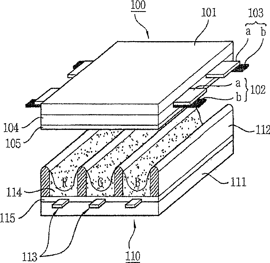
[0043] The plasma display panel 400 forms scan electrodes (Y 1 to Yn) and sustain electrodes (Z) and, above-mentioned scan electrodes (Y 1 To Yn) and sustain electrodes (Z) intersecting complex address electrodes (X 1 to Xm).

[0044] The data driving unit 410 provides the address electrodes (X) formed on the plasma display panel 400 1 Enter data on Xm). The data here is video signal data processed by a v...


PUM


Abstract

A plasma display device and a driving method thereof are provided to stably drive a plasma display panel by applying erase pulses to scan electrodes, sustain electrodes, and address electrodes. A plasma display device includes a plasma display panel(400) and a driving unit(410,420,430). The plasma display panel includes a plurality of scan electrodes, a plurality of sustain electrodes, and a plurality of address electrodes. The driving unit supplies erase pulses to the scan electrodes, the sustain electrodes, and the address electrodes after a sustain period. The erase pulses applied to the scan electrodes are different from the erase pulses applied to the sustain electrodes and the address electrodes.

Description

1. Technical field [0001] The present invention relates to a plasma display device and a driving method thereof, in particular to a plasma display device and a driving method thereof for stably operating a plasma display panel by improving the waveform of an erasing pulse. 2. Background technology [0002] The diaphragm formed between the front panel and the rear panel of a general plasma display panel forms a unit, and each unit is injected with a cycle such as neon (Ne), helium (He) or a mixture of neon and helium (Ne+He). Inert gas with inert discharge gas and a small amount of xenon. When the high-frequency voltage is discharged, the inert gas will generate vacuum ultraviolet rays (Vacuum Ultraviolet rays), which will make the phosphors formed between the partitions emit light and display images. Such a plasma display panel is thin and light, and is popular as a next-generation display device. [0003] figure 1 It is a structural diagram of a general plasma display pa...

Claims


Application Information

Patent Timeline
Patent Type & Authority Patents(China)
IPC IPC(8): G09F9/313H01J17/49G09G3/28G09G3/296G09G3/292
CPCG09G3/292G09G3/296
Inventor 共炳球曺圭春
Owner LG ELECTRONICS(NANJING) PLASMA CO LTD
Features
  • R&D
  • Intellectual Property
  • Life Sciences
  • Materials
  • Tech Scout
  • Unparalleled Data Quality
  • Higher Quality Content
  • 60% Fewer Hallucinations
Learn More