Electronic device with trimming voltage controlled oscillator
A technology of voltage-controlled oscillators and electronic devices, which is applied to power oscillators, circuits, electrical components, etc., can solve the problems of voltage-controlled oscillator output frequency deviation, high-frequency characteristic limitation, and phase noise deterioration, etc., and achieve qualified improvement efficiency, improve output quality, and reduce material cost
- Summary
- Abstract
- Description
- Claims
- Application Information
AI Technical Summary
Problems solved by technology
Method used
Image
Examples
no. 1 example
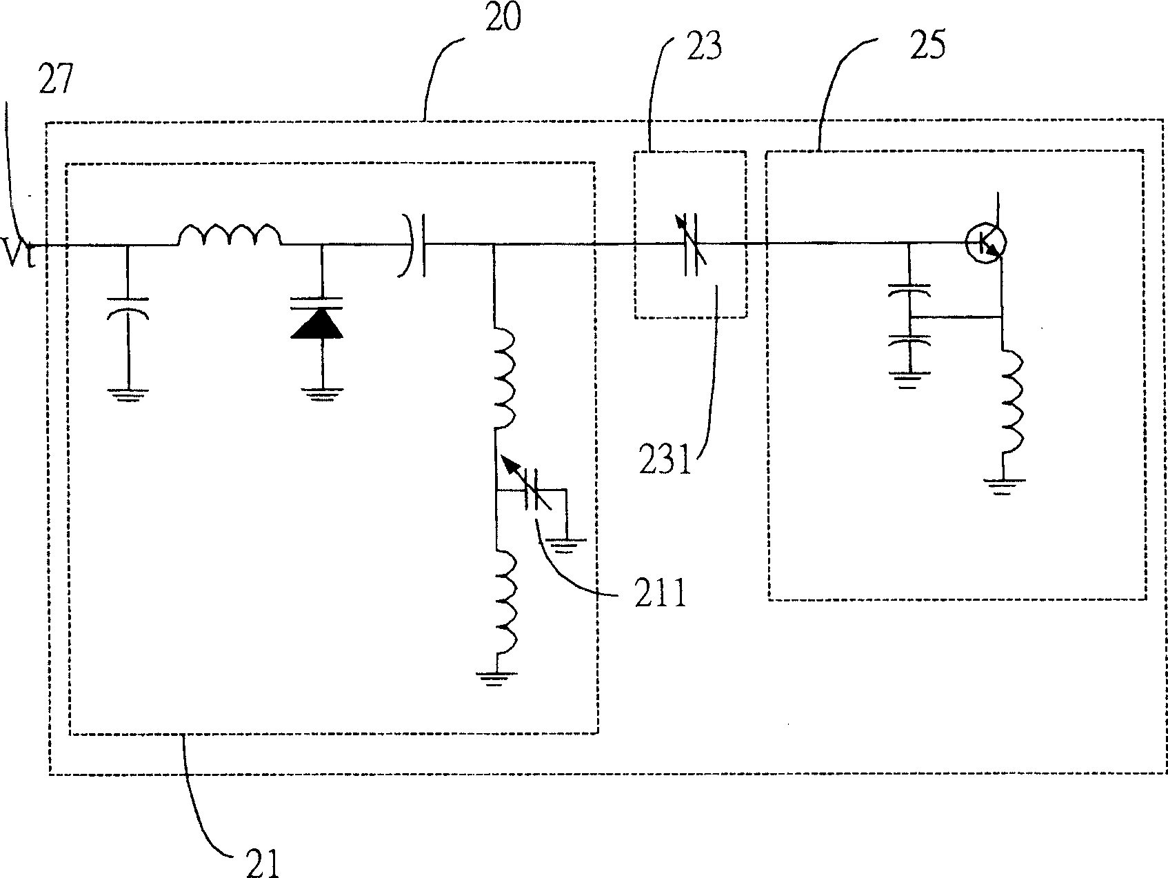
[0058] In this embodiment, the voltage-controlled oscillator mounted on the circuit board of the electronic device is made of an adjustable series microstrip capacitor in the tuning coupling circuit, such as figure 2 The adjustable capacitor 231 is used to adjust the phase noise of the VCO during the manufacturing process.
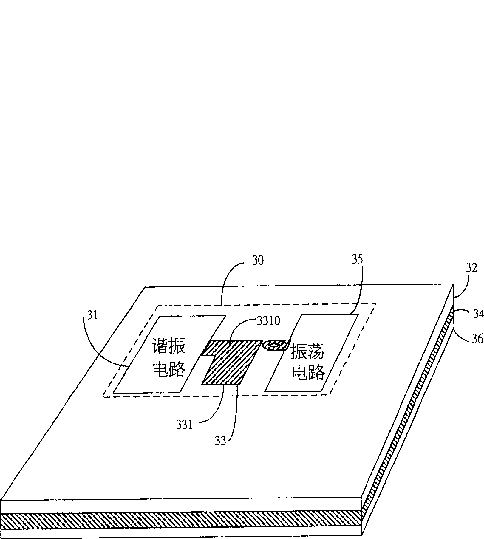
[0059] Please refer to image 3 , image 3 It is a circuit board structure of a voltage-controlled oscillator 30 . Such as image 3 As shown, the voltage controlled oscillator 30 includes a resonance circuit 31 , a coupling circuit 33 and an oscillation circuit 35 . The circuit structure of resonant circuit 31, coupling circuit 33 and oscillating circuit 35 can refer to figure 2 The schematic diagram of the circuit is shown.
[0060] First, a plurality of microstrips are formed by patterning the first conductive layer 32 . These microstrips are conductive and are used to connect the circuit components of the resonant circuit 31 , the coupling circu...
no. 2 example
[0068] In this embodiment, the voltage-controlled oscillator mounted on the circuit board of the electronic device is made by adjusting the adjustable parallel microstrip capacitor in the resonant circuit, such as figure 2 The adjustable microstrip capacitor 211 is used to adjust the output frequency of the voltage-controlled oscillator during the manufacturing process.
[0069] Please refer to Figure 6A , which shows a circuit board structure and circuit of a voltage-controlled oscillator 40 . The VCO 40 includes three parts: a resonant circuit, a coupling circuit and an oscillating circuit. For the circuit structure of resonant circuit, coupling circuit and oscillation circuit, please refer to figure 2 The schematic diagram of the circuit is shown.
[0070] In this embodiment its circuit structure is as follows. First, the first conductive layer 42 is patterned to form a plurality of microstrips. These microstrips are electrically conductive and are used to connect c...
no. 3 example
[0079] In addition to the above-mentioned two embodiments where the adjustable microstrip capacitors are arranged on the coupling circuit and the resonant circuit respectively, another embodiment is to arrange the adjustable microstrip capacitors on the coupling circuit and the resonant circuit at the same time.
[0080] That is to say, the third embodiment is a combination of the first embodiment and the second embodiment. Please refer to Figure 8A , this figure shows a circuit board combining the first embodiment and the second embodiment. On this circuit board, there are adjustable microstrip capacitors 211 and 231 composed of microstrips, respectively arranged in the coupling circuit and the resonant circuit of the voltage controlled oscillator. Wherein, the adjustable microstrip capacitor 211 can be cut at different positions to provide different coupling capacitances to obtain the lowest phase noise. As for the adjustable microstrip capacitor 231, it can be cut in the...
PUM
 Abstract
Description
Claims
Application Information
 - R&D
- Intellectual Property
- Life Sciences
- Materials
- Tech Scout
- Unparalleled Data Quality
- Higher Quality Content
- 60% Fewer Hallucinations
Browse by: Latest US Patents, China's latest patents, Technical Efficacy Thesaurus, Application Domain, Technology Topic, Popular Technical Reports.
© 2025 PatSnap. All rights reserved.Legal|Privacy policy|Modern Slavery Act Transparency Statement|Sitemap|About US| Contact US: help@patsnap.com


