
Double-side organic luminescence display device and its making method

A technology of light-emitting display and manufacturing method, which is applied in the field of double-sided organic light-emitting display device and its manufacturing, and can solve problems such as cost burden and the like

Active Publication Date: 2009-06-10
AU OPTRONICS CORP
View PDF4 Cites 0 Cited by
  • Summary
  • Abstract
  • Description
  • Claims
  • Application Information

AI Technical Summary

Problems solved by technology

In this way, regardless of the cost and process man-hours, it needs twice that of a single display. These two double-sided display technologies are only general assembly without any special advantages. In addition to burdening the cost, they also lose the current The light, thin, short and small requirements pursued by electronic products

Method used


Image

  • Double-side organic luminescence display device and its making method
  • Double-side organic luminescence display device and its making method
  • Double-side organic luminescence display device and its making method

Examples


Embodiment Construction

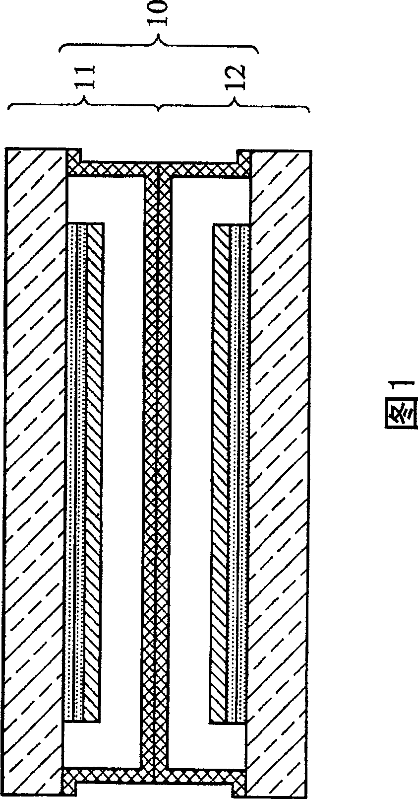
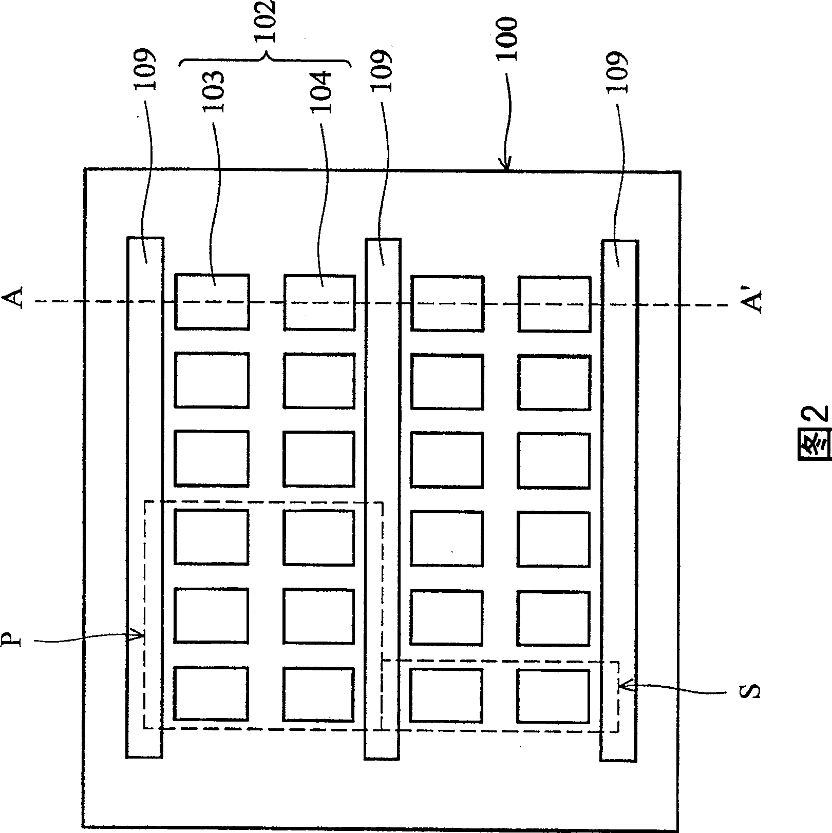
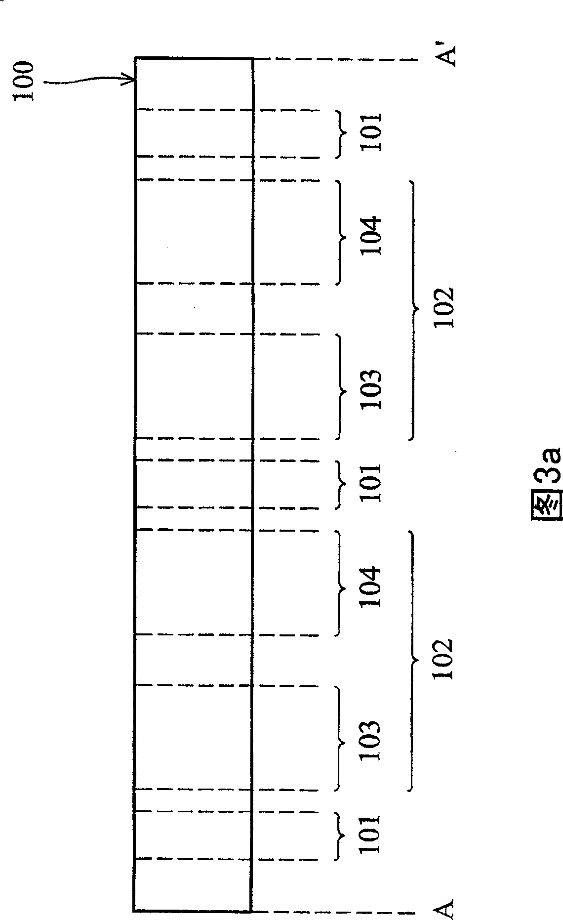
[0070] Please refer to FIG. 2 and FIG. 3a to FIG. 3f. The above figures show the process flow of the double-sided organic light emitting display device according to a preferred embodiment of the present invention. FIG. 2 is a top view, and FIGS. 3 a to 3 f are cross-sectional structural views corresponding to the cut line A-A' of FIG. 2 .

[0071] First, referring to FIG. 2 and FIG. 3 a , a substrate 100 is provided, the substrate 100 has a plurality of non-display regions 101 and display regions 102 , and two adjacent display regions 102 are separated by the non-display region 101 . Wherein, the display area 102 further includes an upward-emitting display area 103 and a downward-emitting display area 104 . In this embodiment, three adjacent upward-emitting display areas 103 (which can each emit light in the three primary colors of RGB) and three adjacent downward-emitting display areas 104 (which can each emit light in the three primary colors of RGB) form a pixel P , and th...


PUM


Abstract

The invention provides a diprosopia organic lightening display device and its manufacturing method. Said diprosopia organic lightening display device includes: base plate; several shelter walls which are parallel with each other are formed on the base plate; upwards lightening display unit and downwards lightening display unit are formed on the base plate equipped with shelter wall; and metal layer which is formed on the shelter wall and connected with the cathode of the downwards lightening display unit. The invention can simplify the craft, decrease one mask, and the shelter wall possesses definite altitude, it can avoid the scotoma generated by mask layer or encapsulation when RGB plating.

Description

technical field [0001] The present invention relates to an organic light emitting display device and a manufacturing method thereof, in particular to a double-sided organic light emitting display device and a manufacturing method thereof. Background technique [0002] A liquid crystal display (LCD) is currently one of the more fully developed and widely used flat panel displays. However, due to the shortcomings of liquid crystal displays such as narrow viewing angle, slow signal response time, and non-self-illuminating light sources, the liquid crystal display cannot quickly display (switch) images, and must consume extra power to supply the backlight, which greatly limits its performance. , resulting in many limitations in its application. [0003] In order to further meet the market demand for flat display panels, the industry has developed an organic electroluminescent display panel to replace the traditional liquid crystal display. Different from liquid crystal display...

Claims


Application Information

Patent Timeline
Patent Type & Authority Patents(China)
IPC IPC(8): H01L27/32H01L21/82H05B33/12H05B33/10G09F9/30
Inventor 赵清烟
Owner AU OPTRONICS CORP
Learn More