
Image forming device

An image and storage device technology, applied in the direction of developing and printing devices, transportation and packaging, photosensitive materials, etc., can solve the problems of reducing the overall processing capacity of the device, increasing the size of the accommodating space 107, and increasing the size of the image forming device, so as to ensure buffering. , Improve processing speed and improve efficiency

Inactive Publication Date: 2009-06-17
NORITZ CORP
View PDF5 Cites 0 Cited by
  • Summary
  • Abstract
  • Description
  • Claims
  • Application Information

AI Technical Summary

Problems solved by technology

However, when printing on photo paper with a long print size, it is necessary to provide a pre-exposure buffer or a post-exposure buffer corresponding to the print size, so that the transport path becomes longer or the storage space 107 becomes larger accordingly. This leads to an increase in the overall size of the image forming apparatus
[0007] In this regard, for example, it is conceivable to wind a long strip of photographic paper into a cylindrical shape and store it temporarily, but in the structure of winding and storing the above-mentioned photographic paper, it cannot be processed until the stored photographic paper enters the next process. The processing of the next photo paper, so the processing of the photo paper will stagnate in the storage section, thereby reducing the overall processing capacity of the device

Method used


Image

  • Image forming device
  • Image forming device
  • Image forming device

Examples


Embodiment 1

[0070] [Overall composition of the photo processing system]

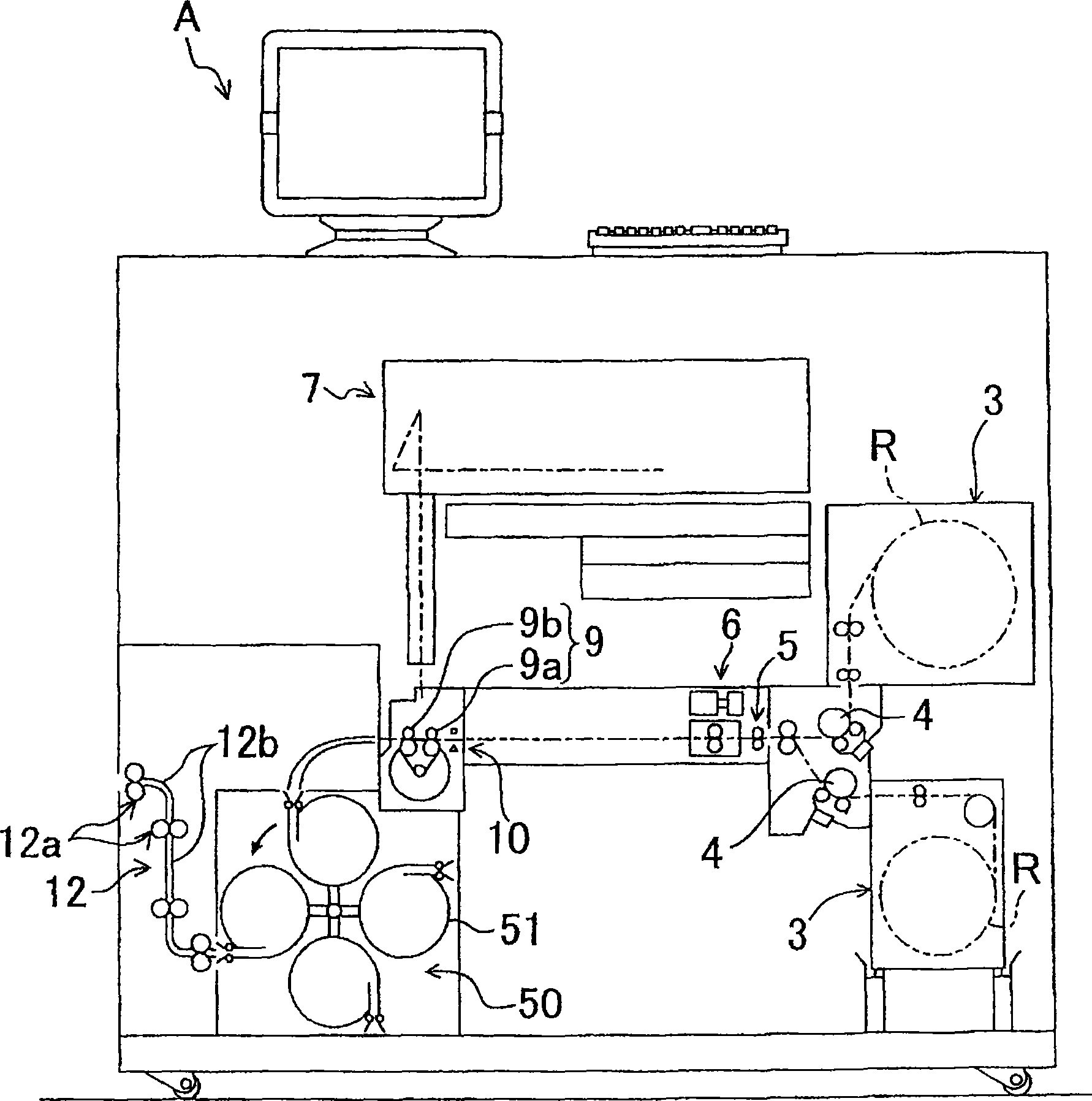
[0071] figure 1 It is a partial cross-sectional view of a photograph processing system including an image forming apparatus A related to the present invention. figure 1 The photo processing system shown has the functions of acquiring image data, developing and exposing images on the latex side (equivalent to imaging surface) of photographic paper (equivalent to imaging medium) according to the image data, and printing photos. This photo processing system includes a film scanner (not shown in the figure) and a medium reading unit (not shown in the figure). The film scanner is used to scan the frame image formed on the developed photographic film to obtain image data, and the media reading unit is used to read the image data stored in the digital camera storage medium or other storage medium.

[0072] figure 1 The illustrated paper cassettes (supply parts) 3 contain cylinders R of long strips of photographic pap...

Embodiment 2

[0116] Fig. 9 shows a photograph processing system having an image forming apparatus A' related to the second embodiment. The difference between Embodiment 2 and Embodiment 1 is that a photographic paper storage mechanism (storage device, second storage device) 60 is provided on the upstream side of the exposure device 7, so the same symbols are attached to the same parts and their descriptions are omitted. Only the different parts are described. Also in this embodiment, the maximum processable length of the photographic paper is longer than the conveying length before exposure and the conveying length after exposure.

[0117] A paper storage mechanism 60 is provided between the conveying unit 6 and the exposure device 7, wherein the conveying unit 6 is used to send the photographic paper P cut into a predetermined size by a cutter (cutting unit) to the downstream side. The photo paper storage mechanism 60 includes a plurality of cylindrical cylindrical parts 61, an approxima...


PUM


Abstract

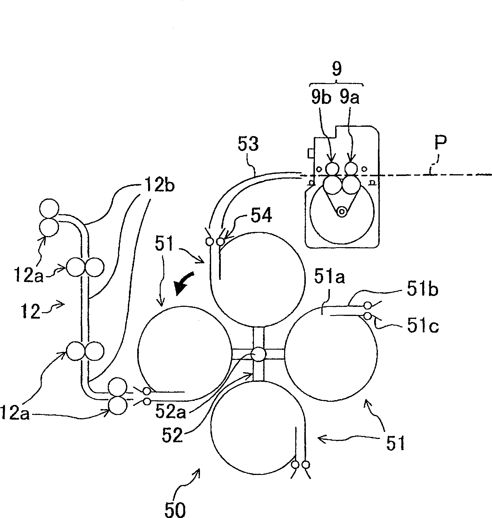
A photographic paper storage part 50 used for accommodating photographic paper P temporarily is arranged on the downstream side of an exposure device used for scanning and exposing on photographic paper P. Said photographic paper storage part 50 consists of a plurality of tubular elements 51, connection elements 52 used for connecting said tubular elements, an electromotor used for rotating said connection elements 52, and the like. Exposed photographic paper P is received temporarily in cylinder shape in said tubular elements 51 and transferred to a feeding unit 12 in the downstream side. Then a buffer part necessary for the exposed photographic paper P is ensured without maximization of the whole equipment. Furthermore, the processing speed is capable of being improved because the exposal process of the next photographic paper is capable of being performed alone whether the tubular elements 51 storing photographic paper is transferred to the next process by storing a plurality of exposed photographic paper at one time through a plurality of tubular elements 51.

Description

technical field [0001] The present invention relates to an image forming apparatus, and more particularly to an image forming apparatus including an image forming unit that forms an image on an image forming surface while conveying an image forming medium by a conveying mechanism. Background technique [0002] As the image forming apparatus used for film development is known, there is an apparatus that performs image exposure on photographic paper (for example, photosensitive paper or the like, which corresponds to an imaging medium) using laser light. Figure 12 An example of the device is shown. The device is set to read the frame image data formed on the developed film or the image data stored in various storage media, and perform image developing and exposure on the latex side of the photographic paper according to the image data. [0003] Such as Figure 12 As shown, the photo paper cassette 100 contains photo paper wound into a cylinder. The photo paper extracted from...

Claims


Application Information

Patent Timeline
Patent Type & Authority Patents(China)
IPC IPC(8): G03B27/46G03B27/32G03D13/00B65H1/00
Inventor 森本桂司
Owner NORITZ CORP
Learn More