Restraining gasket for assembling filler box and method for assembling restrained mechanical joint

A technology of stuffing box and gasket, which is applied in the connection of stuffing seal with fluid pressure, mechanical equipment, non-detachable pipe connection, etc., which can solve the benefits of not having stability and increase the factors of buried or trenched installation And other issues

Inactive Publication Date: 2009-06-24
US PIPE & FOUNDRY
View PDF16 Cites 2 Cited by
  • Summary
  • Abstract
  • Description
  • Claims
  • Application Information

AI Technical Summary

Problems solved by technology

In practice the pipe can be run above ground, in these cases such pipe does not have any stability benefit, increasing the factor of buried or trenched installation

Method used


Image

  • Restraining gasket for assembling filler box and method for assembling restrained mechanical joint
  • Restraining gasket for assembling filler box and method for assembling restrained mechanical joint
  • Restraining gasket for assembling filler box and method for assembling restrained mechanical joint

Examples


Embodiment Construction

[0028] The following is a detailed description of the present invention. Those skilled in the art will appreciate that the features presented herein are intended for purposes of illustration against the inventor's most preferred embodiment and should not be construed as limiting the scope of the invention. References herein to "pipe" will equally be understood to refer to any length of pipe, attachment, fitting or any other connecting device or element, regardless of method or material of manufacture.

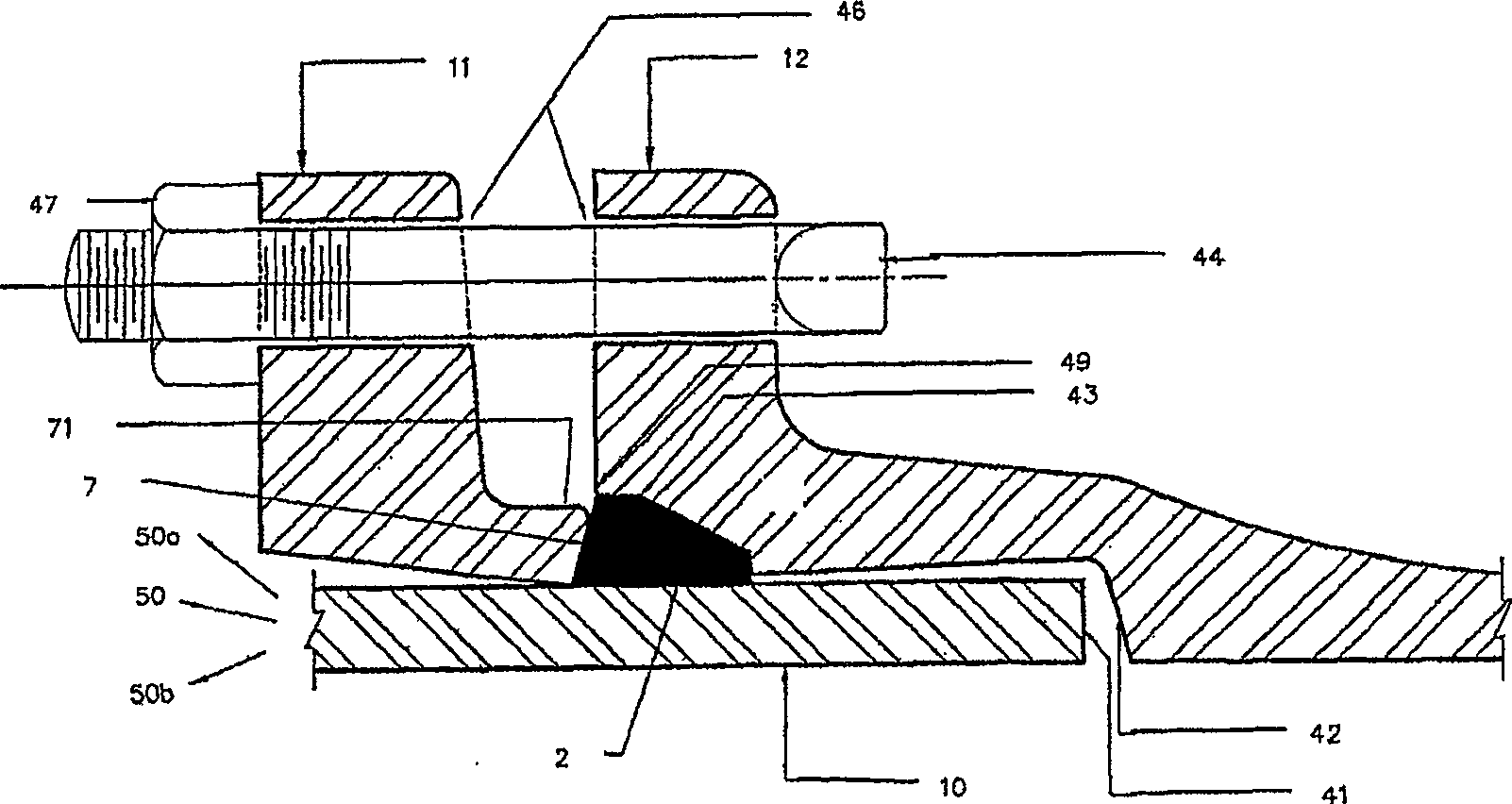
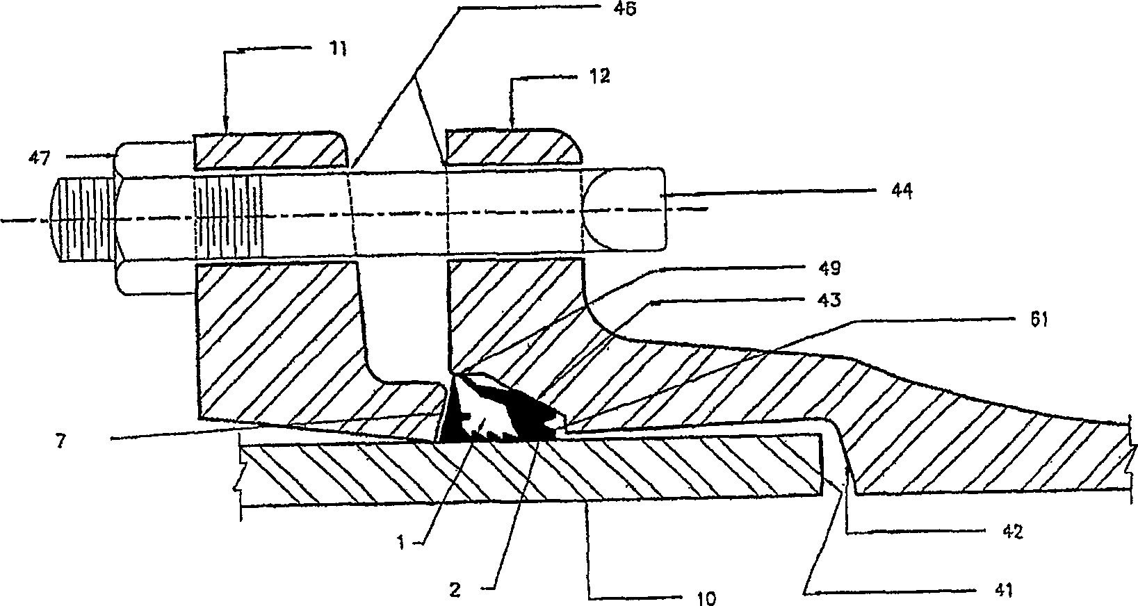
[0029] now go to figure 1 , figure 1 Diagram representing a typical mechanical joint. Assembly of the joint according to the invention is carried out according to techniques known in the art. Specifically, but not limiting to known modifications that will be equally applicable to the present invention as if they were known techniques, the linker contains the following elements satisfying the following relationships. A compression ring or gland 11 is placed on the pipe plug ...


PUM


Abstract

The invention can be basically described as a gasket for converting a standard mechanical joint to a restricted mechanical joint without changing the configuration of the bell, plug or gland of the joint and without additional fittings or equipment. In the practice of the present invention, the bell and gland configuration of a standard mechanical coupling can be used to connect the plug end of one length of pipe to the bell end of another length of pipe in a constrained relationship that exceeds more than The force of friction of the rubber against the tube. In a more specific discussion of the taught embodiments, the invention includes forming the liner to fit within the bell in such a manner that during rest there is a void or groove in which the liner compresses, which in turn affects slice rotation. In this way, the configuration of the pads affects the synchronization and degree of rotation throughout the process of securing the gland to the bell.

Description

technical field [0001] The invention generally relates to connections between lengths of pipe or between pipe and fittings. More specifically, the present invention relates to an apparatus and method for joining two lengths of pipe that maximizes the advantages of constrained push joints as well as mechanical joints, which are well known in the art. The invention can be applied to long run pipe lengths as well as fittings, attachments and joints. Background technique [0002] The industry has largely focused its attention on the maintenance of connections between adjacent lengths of pipe after installation due to thrust, earth's crust and external mechanical forces exerted on the pipe. The result of this focus has been the creation of a library of different protocols and methods known in the art. Most of these solutions can be classified as "push" or "mechanical" joints. References to "pipe" by the inventors in connection with the application or use of the present inventi...

Claims


Application Information

Patent Timeline
Patent Type & Authority Patents(China)
IPC IPC(8): F16L5/02F16L17/00F16L17/06F16L21/04F16L13/04F16LF16L19/08
CPCF16L21/08
Inventor 丹尼尔·艾伯特·科普兰
Owner US PIPE & FOUNDRY
Why Eureka
Try Eureka