
Apparatus for the manufacture of double-walled pipes

A composite tube and tube seat technology, applied in the direction of applications, tubes, rigid tubes, etc., can solve the problems that can only be connected or disconnected as a whole, inaccurate vacuum control, and cannot be vacuum controlled

Active Publication Date: 2009-07-08
尤尼克公司
View PDF5 Cites 0 Cited by
  • Summary
  • Abstract
  • Description
  • Claims
  • Application Information

AI Technical Summary

Problems solved by technology

Finishing mandrels designed with pressure-reduced regions or vacuum regions (which are axially separated by larger vacuum-free regions and which can only be connected or disconnected integrally) mean that between the tube region and Sufficiently precise vacuum control is not possible in the transition region between the socket regions
Defects are prone to form on the inner wall or surface due to imprecise vacuum control in the transition area

Method used


Image

  • Apparatus for the manufacture of double-walled pipes
  • Apparatus for the manufacture of double-walled pipes
  • Apparatus for the manufacture of double-walled pipes

Examples


Embodiment Construction

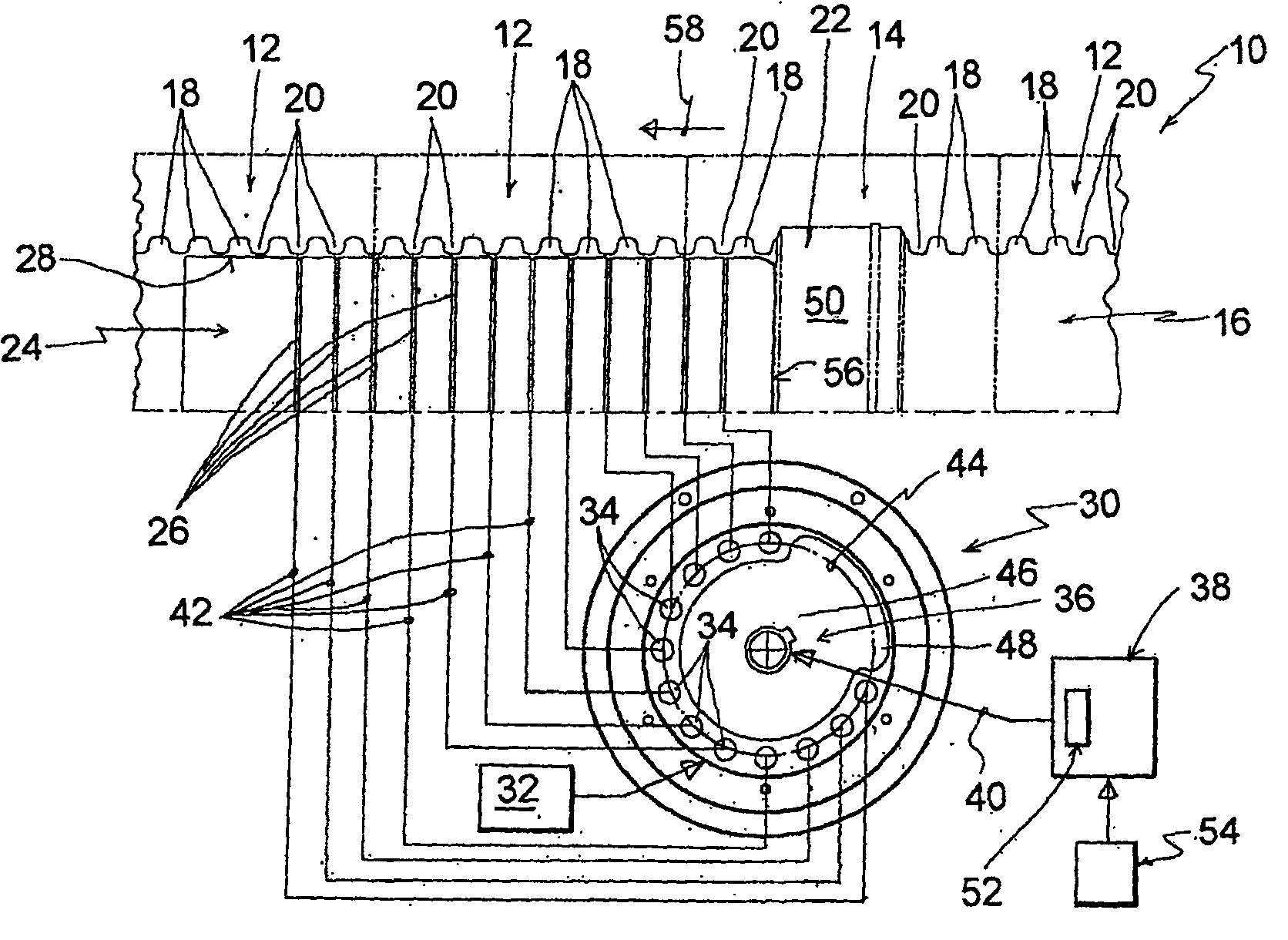
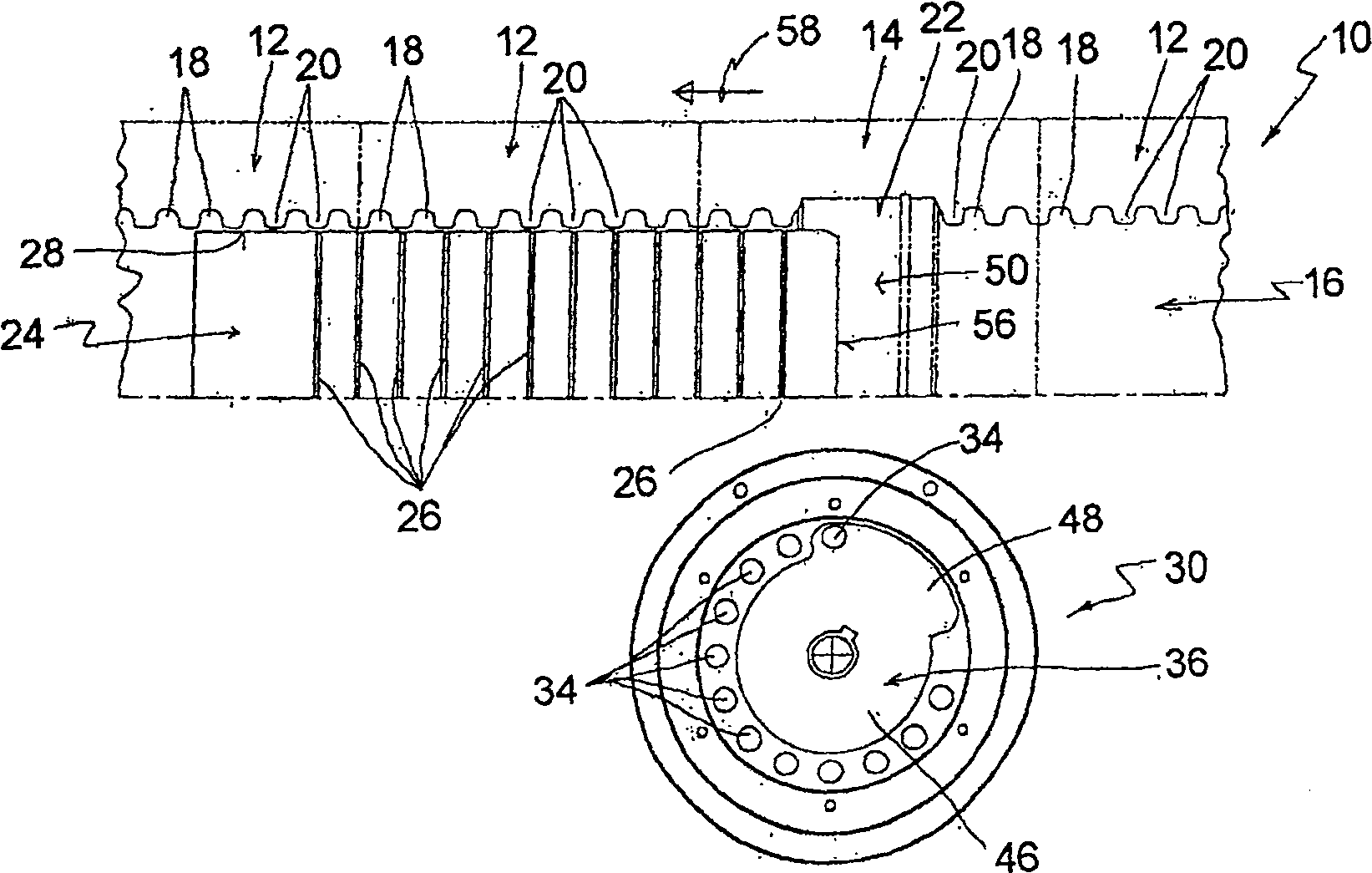
[0022] figure 1 Important details of the device 10 for producing a double-walled composite pipe according to the invention are schematically shown, namely the forming clip halves 12 and 14 . The figure shows three forming clip halves 12 of a row of forming clips. Corresponding forming clip halves 12, 14 are located in a second row (not shown) of forming clip halves opposite this row of forming clip halves 12, 14 so as to form forming channels for the manufacture of double wall composite pipes 16.

[0023] The profiled clip halves 12 positioned opposite each other along the profiled channels 16 are alternately designed with transverse grooves 18 and transverse ribs 20 .

[0024] Forming clip half 14— figure 1 Only one forming clip half 14 is shown in FIG. 2 - designed to have an inner contour 22 corresponding to the base portion of the double-wall composite pipe to be produced. The inner contour 22 adjoins the transverse groove 18 and the transverse ribs 20 on both sides. ...


PUM


Abstract

The machine for making hoses with corrugated sections, which have a smooth inside, and a non-corrugated section (50) has two rows of mold halves. Some of these (14) produce the smooth hose section while the remainder (12) produce the corrugated sections. The smooth inner surface is produced by a calibrating mandrel (24) with vacuum slots (26). A vacuum control unit (30) has holes (34) connected to the slots which can be selectively opened and closed.

Description

technical field [0001] The present invention relates to an apparatus for manufacturing a double-walled composite pipe having at least one finned pipe longitudinal section and having a base section comprising an outer wall having troughs and crests and integrally joined to the smooth inner walls of the troughs of the outer wall, and the outer and inner walls are integrally joined to each other in face-to-face contact along the socket portion, the device has two rows of forming clip halves and a sizing mandrel (sizing mandrel), said forming clip halves form a forming channel for manufacturing a composite pipe along a shared forming section, at least one pair of forming clip halves located opposite each other in the forming section have an inner profile for manufacturing a socket part , while the rest of the forming clip halves are alternately designed to have transverse grooves corresponding to the crests and transverse ribs corresponding to the troughs, the finishing mandrel pr...

Claims


Application Information

Patent Timeline
Patent Type & Authority Patents(China)
IPC IPC(8): B29D23/00F16L9/18B29C51/10B31C99/00B29C48/09B29C48/10B29C48/13B29C48/32B29C48/90B29C48/92
CPCB29C47/908B29C47/902B29C47/0023B29C47/92B29C2791/006B29C49/0021B29L2023/186B29C47/0033B29C48/92B29C48/09B29C48/10B29C48/13B29C48/902B29C48/904B29C48/908B29C2948/92019B29C2948/92428B29C2948/92514B29C2948/92923B29C49/0025
Inventor G·纽鲍尔
Owner 尤尼克公司
Features
  • Generate Ideas
  • Intellectual Property
  • Life Sciences
  • Materials
  • Tech Scout
  • Unparalleled Data Quality
  • Higher Quality Content
  • 60% Fewer Hallucinations
Learn More