
Method for producing an injector

a technology of injectors and injectors, which is applied in the direction of liquid fuel feeders, machines/engines, mechanical equipment, etc., can solve the problems of limiting the form design essentially to cylindrical spray orifices, deviations from the optimal spray pattern of internal combustion engines, and inability to precisely position and design spray orifices, etc., to achieve simple and precise design of spray orifices, good corrosion protection, and flexible replacement

Active Publication Date: 2019-09-05
ROBERT BOSCH GMBH
View PDF39 Cites 0 Cited by
  • Summary
  • Abstract
  • Description
  • Claims
  • Application Information

AI Technical Summary

Benefits of technology

The present invention provides a method for producing an injector that allows for precise positioning and shaping of the spray orifice element, resulting in an optimal injection and combustion in an internal combustion engine. The method is simple and efficient, and provides a high accuracy in the production of the injector.

Problems solved by technology

In a laser drilling process, however, a precise positioning and design of the spray orifices is possible only to a limited extent.
This process, for example, limits the form design essentially to cylindrical spray orifices.
Small inaccuracies in the production of the spray orifices may already result in deviations from the optimal spray patterns for the internal combustion engine.
Consequently, there may be an increase in the production of pollutants, in particular an increased particle formation, and a reduction in the efficiency as a result of a deteriorated combustion in the internal combustion engine.

Method used


Image

  • Method for producing an injector
  • Method for producing an injector
  • Method for producing an injector

Examples


Embodiment Construction

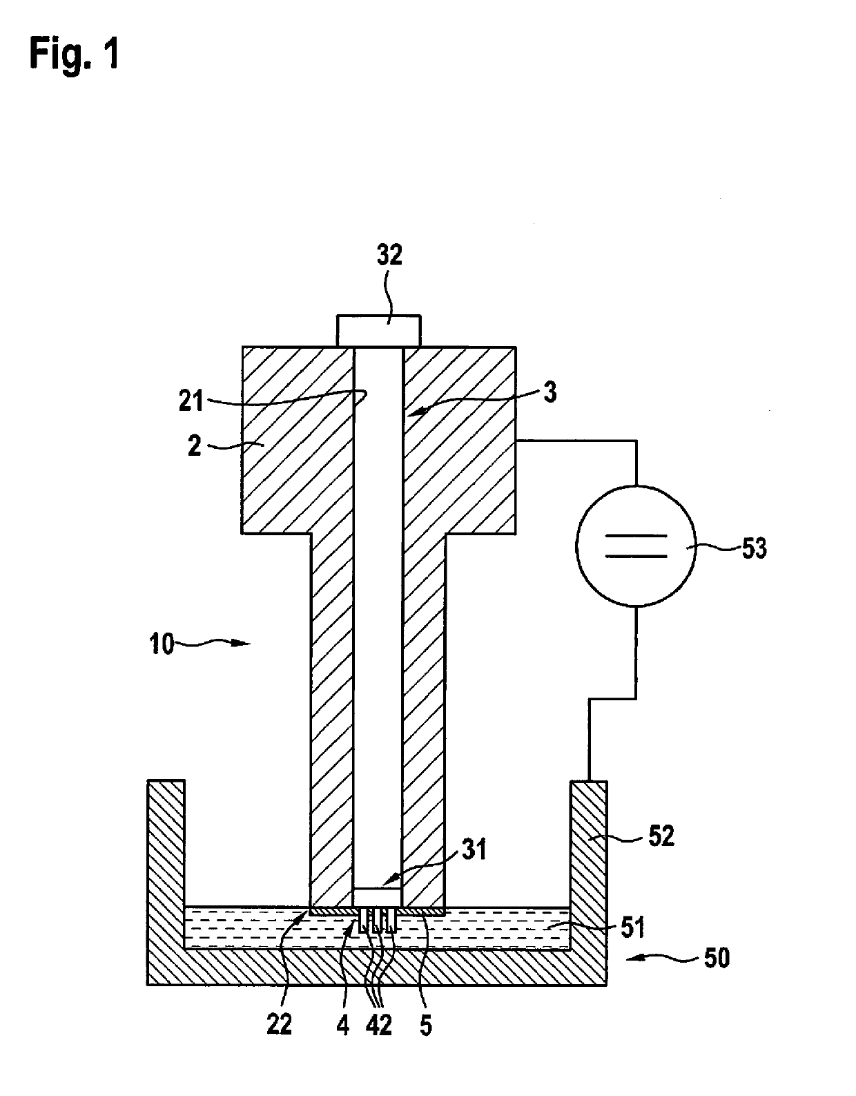
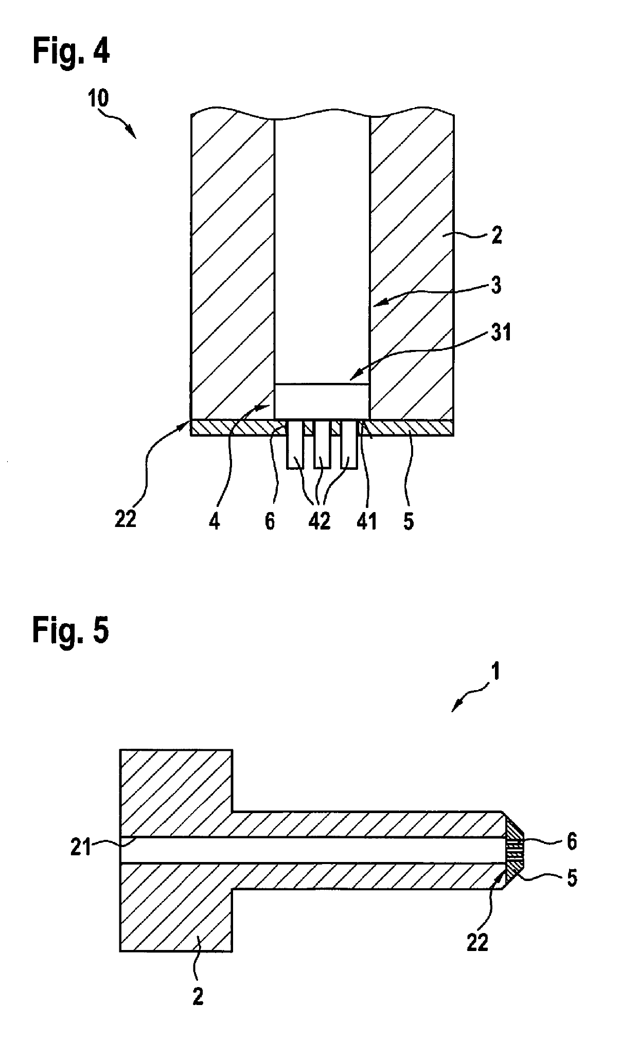
[0039]FIG. 1 shows a method step of the production of an injector 1, a spray orifice element 5 being produced by galvanization on a downstream end 22, in the injection direction, of an injector base element 2. The method is presented at a point in time at which the spray orifice element 5 is already developed as a galvanization layer, that is, directly prior to the end of the galvanization step.

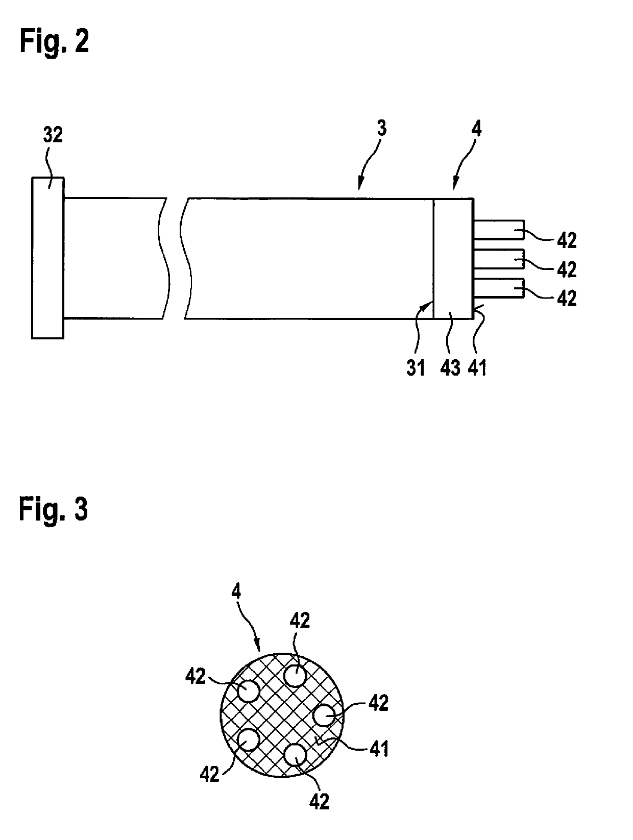
[0040]To produce the spray orifice element 5 from a galvanization layer, an injector assemblage 10 is immersed in a galvanization bath 51 in a vessel 52. Injector assemblage 10 comprises an injector base element 2, a rod 3 and a negative matrix 4 of the spray orifice element 5 that is to be produced. The injector base element 2 is designed as a standard part and may be used as a basis for injectors having different spray orifice elements 5.

[0041]Injector base element 2 is respectively shown in the figures as a sectional drawing, the rod 3 and negative matrix 4 being respectively shown in a no...


PUM


Abstract

A method for producing an injector which is designed in particular to inject fuel into an induction pipe or directly into a combustion chamber of an internal combustion engine. The method includes providing an injector base element, providing a rod that is insertible into a through hole of the injector base element, producing a negative matrix of a spray orifice element on an axial end of the rod, inserting the rod into the through hole of the injector base element, positioning the negative matrix situated on the rod relative to the injector base element, producing the spray orifice element having at least one spray orifice by applying a galvanization layer on a downstream end, in the injection direction, of the injector base element and on the negative matrix, and removing the rod and the negative matrix.

Description

CROSS REFERENCE[0001]The present application claims the benefit under 35 U.S.C. § 119 of German Patent Application No. DE 102018203065.0 filed on Mar. 1, 2018, which is expressly incorporated herein by reference in its entirety.FIELD[0002]The present invention relates to a method for producing an injector, which injects in particular fuel into an induction pipe or directly into a combustion chamber of an internal combustion engine, and to an injector of this kind.BACKGROUND INFORMATION[0003]Injectors for internal combustion engines are available in the related art in various embodiments. Conventionally, spray orifices are provided on injector outlets for injecting and dispersing the fuel. Normally, such spray orifices are produced by laser drilling. In a laser drilling process, however, a precise positioning and design of the spray orifices is possible only to a limited extent. This process, for example, limits the form design essentially to cylindrical spray orifices. Small inaccur...

Claims


Application Information

Patent Timeline
Patent Type & Authority Applications(United States)
IPC IPC(8): F02M61/14F02M69/04
CPCF02M61/14F02M2200/85F02M69/044F02M61/168F02M61/1806
Inventor STACH, THOMASDOETSCH, JAMESTREMEL, JANFEIGL, MARKUSRUECK, PETERPOLTORATSKI, ROMANDEHM, TIMO
Owner ROBERT BOSCH GMBH
Features
  • Generate Ideas
  • Intellectual Property
  • Life Sciences
  • Materials
  • Tech Scout
  • Unparalleled Data Quality
  • Higher Quality Content
  • 60% Fewer Hallucinations
Learn More