


Quick Research
Generate reliable direction feasibility study reports for your R&D in just a few steps.

Technical Q&A
Discover and master advanced knowledge NOW. Basics, ideas, possibilities, all at once.

Find Solutions
As an expert in R&D theories, this can generate solutions to your technical problems instantly.

Evaluate Feasibility
Analyze your overall solution with one click, know your potential R&D risks in advance.

Monitor Landscape
Get weekly tech updates, stay abreast of the latest tech innovations and key insights.
Pneumatic tire
A technology for pneumatic tires and tires, applied in tire parts, tire treads/tread patterns, transportation and packaging, etc., can solve the problem of reduced central rib rigidity, inability to simultaneously improve handling stability and wet skid resistance, and handling stability. It can achieve high ground pressure, provide anti-wet-slip drainage, and improve wet-slip performance.
- Summary
- Abstract
- Description
- Claims
- Application Information
AI Technical Summary
Problems solved by technology
Method used
Image

Examples
no. 1 Embodiment approach 〕
[0131] Next, a first embodiment of the present invention will be described in detail with reference to the drawings.
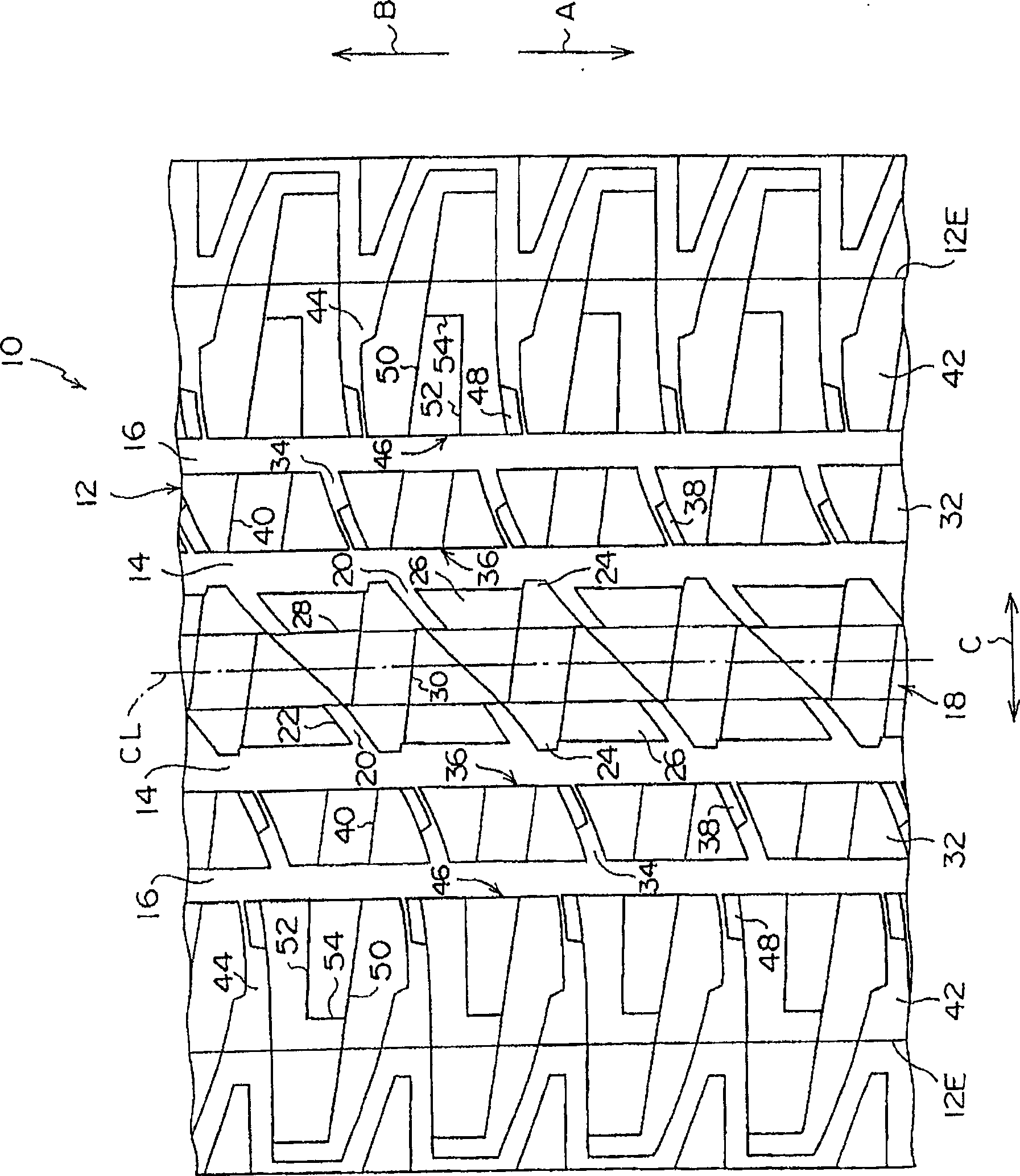
[0132] Such as figure 1 As shown, on the tread 12 of the pneumatic tire 10 of the present embodiment, on both sides of the equatorial plane CL of the tire, there are respectively formed along the tire circumferential direction (the direction of the arrow A (the direction of the tire rotation in this embodiment) and the direction of the arrow B respectively. The central circumferential main groove 14 extending in the tire axial direction is formed on the outer side of the central circumferential main groove 14 in the tire axial direction, and the side circumferential main groove 16 extending along the tire circumferential direction is formed.
[0133] In addition, since the structure of the pneumatic tire 10 of this embodiment is the same as that of a general radial tire, description of its internal structure is omitted.
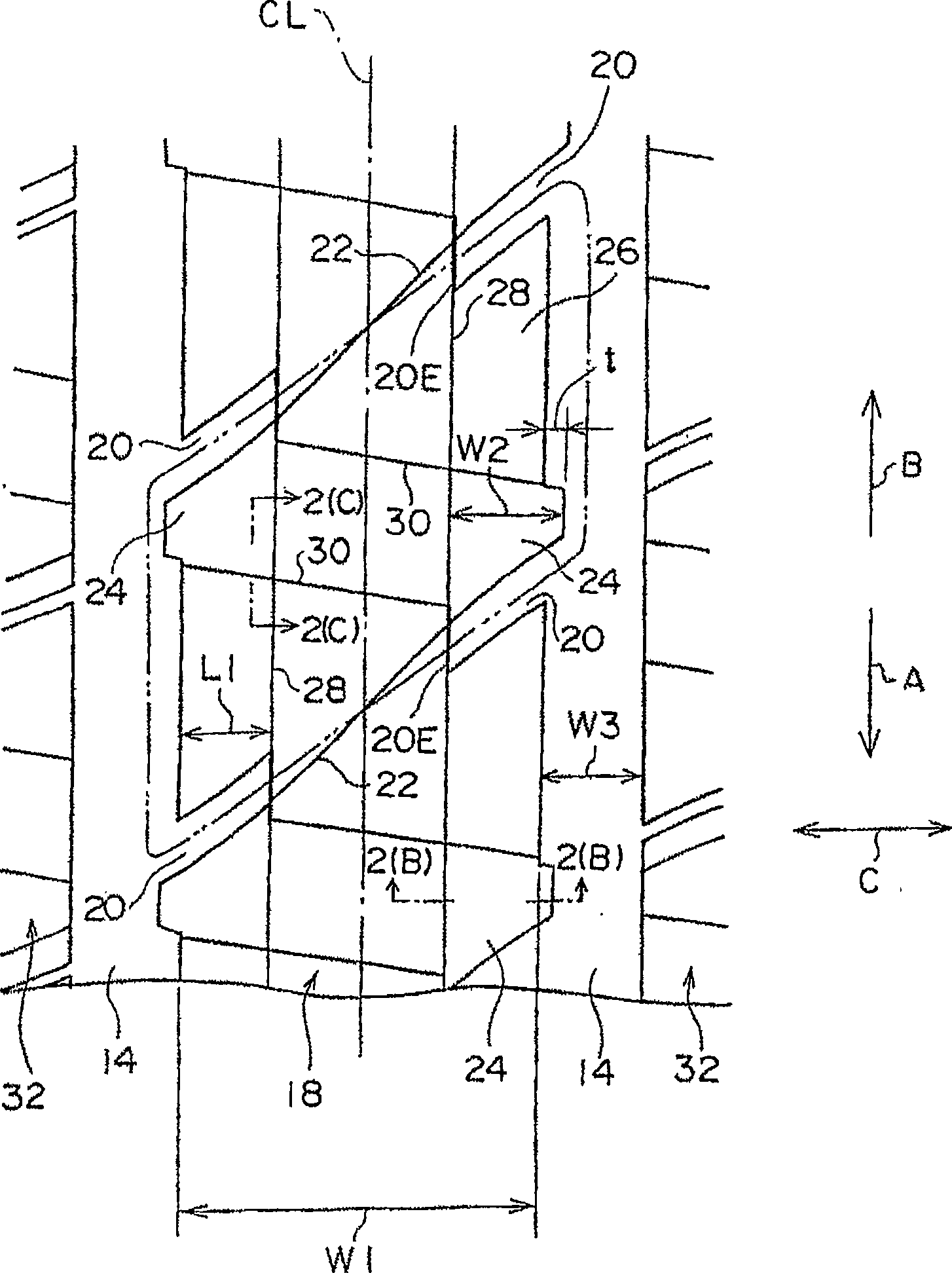
[0134] (central bulge column)
[013...
no. 2 Embodiment
[0231] Below, refer to Figure 7 and Figure 8 A second embodiment of the present invention will be described. The same structures as those in the first embodiment are assigned the same symbols, and descriptions thereof are omitted.
[0232] Such as Figure 7 As shown, the pneumatic tire 60 of the present embodiment differs in the size of the central protrusion row chamfer 24 from that of the first embodiment.
[0233] The central protrusion row chamfered portion 24 of the present embodiment is formed only on a portion of the circumferentially adjacent non-chamfered portion 26 protruding from the end portion on the central circumferential main groove 14 side.
[0234] Such as Figure 8 As shown, in the center protrusion row 18, the groove wall 24S on the tire axial side of the portion protruding toward the central circumferential main groove 14 side at the tire axial position, and the groove wall on the tire axial side of the non-chamfered portion 26 26S is connected to t...
PUM
 Abstract
Description
Claims
Application Information
 - R&D Engineer
- R&D Manager
- IP Professional
- Industry Leading Data Capabilities
- Powerful AI technology
- Patent DNA Extraction
Browse by: Latest US Patents, China's latest patents, Technical Efficacy Thesaurus, Application Domain, Technology Topic, Popular Technical Reports.
© 2024 PatSnap. All rights reserved.Legal|Privacy policy|Modern Slavery Act Transparency Statement|Sitemap|About US| Contact US: help@patsnap.com