Injection molding nozzle

A nozzle and nozzle body technology, applied in the field of die-casting nozzles, can solve the problems of damage, unsealing, and the centering sleeve cannot be kept close to the cavity of the mold, so as to reduce the risk of cold blockage and achieve the effect of good thermal separation.

Inactive Publication Date: 2009-07-15
GUENTHER HEISSKANALTECHNIK GMBH
View PDF2 Cites 0 Cited by
  • Summary
  • Abstract
  • Description
  • Claims
  • Application Information

AI Technical Summary

Problems solved by technology

[0010] The disadvantage of this is that both the spray head and the centering sleeve are fixedly mounted in the nozzle body, preventing rapid replacement of wear parts
In addition, the extremely tight fit in the mold parts creates a large number of problems during installation, in particular expansion joints must be left between the centering sleeve and the shoulder in the mold cavity to compensate for the thermal expansion of the nozzle body
If the centering sleeve is not accurately controlled by an extremely tight fit in the mold cavity, damage can occur when the hot runner nozzle heats up, especially if the centering sleeve is warped
Another disadvantage is that the centering sleeve cannot always be close to the mold cavity, i.e. the sealing seat is in the mold part
Since the closing pin can only close the very short cylindrical part of the casting hole, leaks can occur very quickly, especially due to thermal expansion which is difficult to control

Method used


Image

  • Injection molding nozzle
  • Injection molding nozzle
  • Injection molding nozzle

Examples


Embodiment Construction

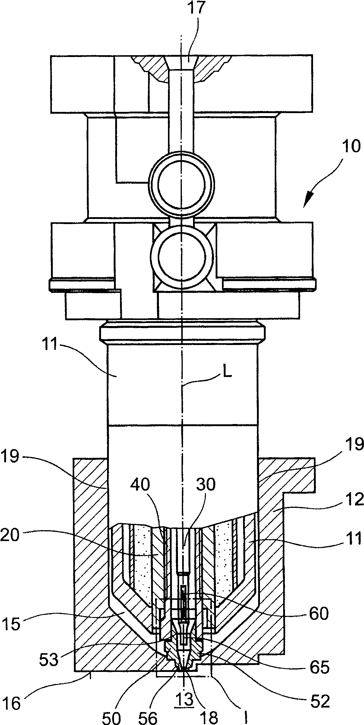
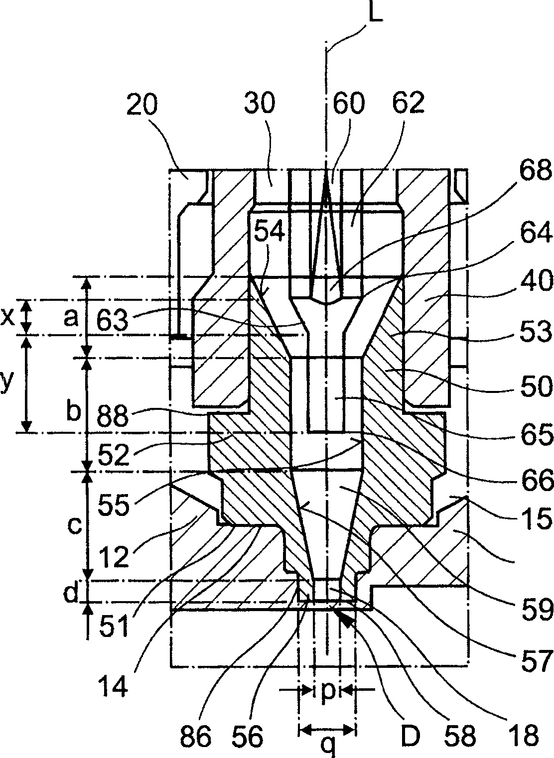
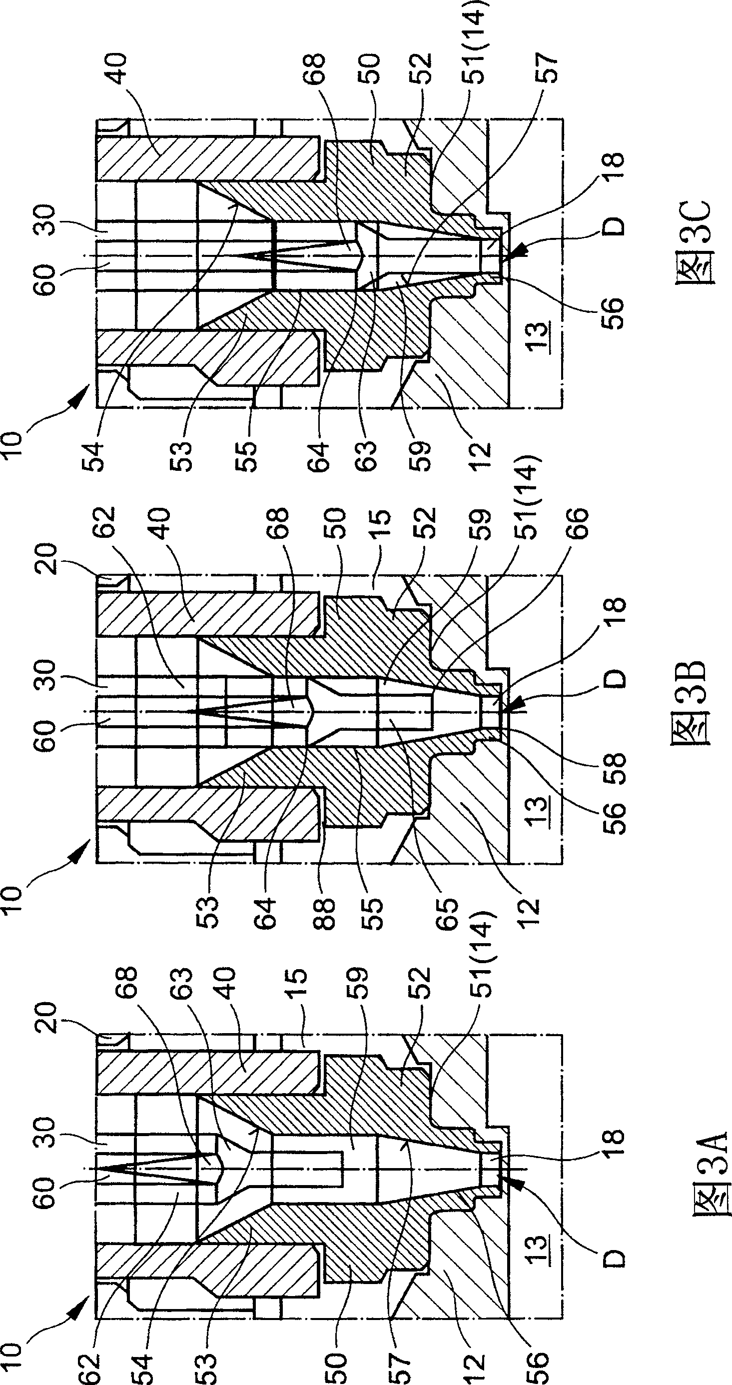
[0030] figure 1 The die-casting nozzle designated 10 as a whole is designed as a needle-shaped shut-off nozzle and is a component of the die-casting tool (not shown). It has a preferably externally heated nozzle body 20 in the housing 11 , which forms a flow channel 30 concentrically to the longitudinal axis L on the inside. The melt to be processed, for example a metal, silicon or plastic melt, is conveyed from the material delivery opening 17 to the mold cavity (not shown in detail) via the flow channel 30 . The latter is formed between form parts 12 , 13 fastened to a formwork (not shown).

[0031] A spray head 40 made of a highly thermally conductive material is preferably screwed into the nozzle body 20 , which continues the melt channel 30 downwards. The spray head 40 , the nozzle body 20 , the housing 11 and the form part 12 delimit an air gap 15 which thermally separates the needle-shaped closing nozzle 10 and the form part 12 from each other. The housing 11 of the ...


PUM


Abstract

An injection moulding nozzle (10) for use in an injection moulding tool, comprises a body (20), at least one flow channel (30) for an injection moulding compound, and a nozzle mouthpiece (40). The latter contains an insert (50) which can be moved longitudinally, and which is clamped between the nozzle body and a mould insert during operation. The insert has a neck which can be placed in the nozzle mouth piece, and a flange which is supported on the insert. The nozzle mouthpiece, which surrounds the upper part of the insert, can be screwed from underneath into the nozzle body.

Description

technical field [0001] The invention relates to an injection casting nozzle for use on an injection molding tool according to the preamble of claim 1 . Background technique [0002] For feeding flowable material, in particular melt, to mold components (mold parts), die-casting nozzles are generally used, in particular hot or cold-runner nozzles. Most of these nozzles have a thermostatic nozzle body, in which flow channels or melt channels are formed, which open on or into the spray head and are fluidly connected to the mold cavity of the die-casting tool formed by the mold parts. In order to keep the melt at a uniform temperature up to the mold parts, the spray head, which is fixedly inserted into the nozzle body from below, consists of a highly thermally conductive material. An air gap is formed between the die casting nozzle and the mold for thermal separation. [0003] A disadvantage of this is that the wear of the spray head is rather high, especially when processing m...

Claims


Application Information

Patent Timeline
Patent Type & Authority Patents(China)
IPC IPC(8): B29C45/27B29C45/28
CPCB29C2045/2798B29C45/278B29C45/2711B29C45/2806B29C45/27B29C45/28
Inventor 赫伯特·君特约翰内斯·彼得鲁斯·范利斯豪特
Owner GUENTHER HEISSKANALTECHNIK GMBH
Why Eureka
Try Eureka