Low-oil-pressure bar rapid automatic cut-off machine

An automatic cutting, low oil pressure technology, applied in the direction of shearing devices, accessories of shearing machines, shearing machine equipment, etc. The effect of yaw, fast replacement and stable hydraulic speed

Pending Publication Date: 2021-08-27
浙江精勇精锻机械有限公司
View PDF0 Cites 0 Cited by
  • Summary
  • Abstract
  • Description
  • Claims
  • Application Information

AI Technical Summary

Problems solved by technology

Now most of the market is using the mechanical method, the dynamic unbalanced state of the cutter in motion or the error of manufacturing and human adjustment will make the actuating position of the cutter deviate from the theoretical design value, the mechanical cutting method No holding force, directly give force to cut or call shearing, its surface inclination is too large, can not effectively meet the accuracy of today's forging industry, although it can meet the production requirements, the speed is fast, but after the material is cut, the cross-section inclination is serious , for the forging industry, some products are not applicable; the disadvantage of the cutting machine is that the section is not flat, and the circular saw is flat and smooth but the speed is slow
The two cannot co-exist effectively

Method used


Image

  • Low-oil-pressure bar rapid automatic cut-off machine

Examples


Embodiment Construction

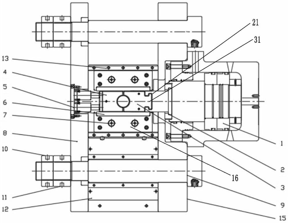
[0028] In order to make the purpose, technical solutions and advantages of this application clearer, the technical solutions in the embodiments will be clearly and completely described below in conjunction with the accompanying drawings in the embodiments. Obviously, the described embodiments are only a part of the application Examples, not all examples. Based on the given embodiments, all other embodiments obtained by persons of ordinary skill in the art without creative efforts fall within the protection scope of the present application.

[0029] In the description of the present application, it should be understood that the orientation or positional relationship indicated by the terms "upper", "lower" and the like is based on the orientation or positional relationship shown in the drawings, and is only for the convenience of describing the present application and simplifying the description, It is not intended to indicate or imply that the device or element referred to must...


PUM


Abstract

The invention discloses a low-oil-pressure type bar rapid automatic cut-off machine which comprises: a machine frame; a cutter; an auxiliary cutter which is arranged opposite to the cutter; a cutter driving assembly, wherein the cutter is connected to the output end of the cutter driving assembly, and the output end of the cutter driving assembly moves to drive the cutter to do linear reciprocating motion; an auxiliary cutter driving assembly which is fixedly arranged at the output end of the auxiliary cutter driving assembly, wherein the auxiliary cutter is driven by movement of the output end of the auxiliary cutter driving assembly to synchronously get close to the cutter or synchronously get away from the cutter, and deflection of the cutter can be effectively reduced due to the fact that the gap between the cutter and the guide rail is stable.

Description

technical field [0001] The invention belongs to the technical field of cutting devices, and in particular relates to a low oil pressure type fast automatic cutting machine for bar materials. Background technique [0002] The design structure of the hydraulic cutting machine is that the hanging knife, cutting knife, auxiliary knife, oil cylinder are matched with the hydraulic machine, and the material rack feeding mechanism is combined to form a complete system. Use the low pressure oil pressure to push the oil cylinder, connect the hanging knife to drive the cutting knife, and add an auxiliary knife opposite to make it reciprocate, and the two move to hold the material at the same time for cutting. In order to make the cutter smooth and smooth, the structure is guided on four sides to reduce the deflection force generated when the cutter cuts the material and improve the service life of the cutter. Now most of the market is using the mechanical method, the dynamic unbalance...

Claims


Application Information

Patent Timeline
Patent Type & Authority Applications(China)
IPC IPC(8): B23D15/02B23D15/14B23D33/00
CPCB23D15/02B23D15/14B23D33/00
Inventor 陈炯亨林东民陈俞廷
Owner 浙江精勇精锻机械有限公司
Why Eureka
Try Eureka