A circular curved surface flow calibration tool

A flow and curved surface technology, which is applied in the field of circular surface flow calibration tooling, can solve the problems of difficult to achieve simultaneous calibration of porous positions, low calibration efficiency, poor sealing, etc., to reduce the time for tooling changeover, solve the problem of inability to align, structure concise effect

Active Publication Date: 2021-04-23
BEIJING POWER MACHINERY INST
View PDF6 Cites 0 Cited by
  • Summary
  • Abstract
  • Description
  • Claims
  • Application Information

AI Technical Summary

Problems solved by technology

One orifice corresponds to one flow tooling. A flow tooling includes a positioning block and screws on it. It can be seen that the size of a single tooling is often relatively large. For some orifices with relatively dense distribution, it is impossible to use conventional flow tooling to control each section. The flow holes are all detected, and the scope of use has certain limitations; at the same time, for the orifice on the irregular surface, it is difficult to clamp the conventional flow tooling, and it is also difficult to seal, and the requirements for the operator are high. Poor performance requires repeated disassembly and assembly, time-consuming and labor-intensive, low calibration efficiency, and difficult to achieve simultaneous calibration of porous positions

Method used


Image

  • A circular curved surface flow calibration tool
  • A circular curved surface flow calibration tool
  • A circular curved surface flow calibration tool

Examples


Embodiment 1

[0023] The flow calibration tool of this embodiment includes a positioning ring 3-1, a pressing ring 3-7, a water inlet device 3-6 and a sealing gasket 3-4.

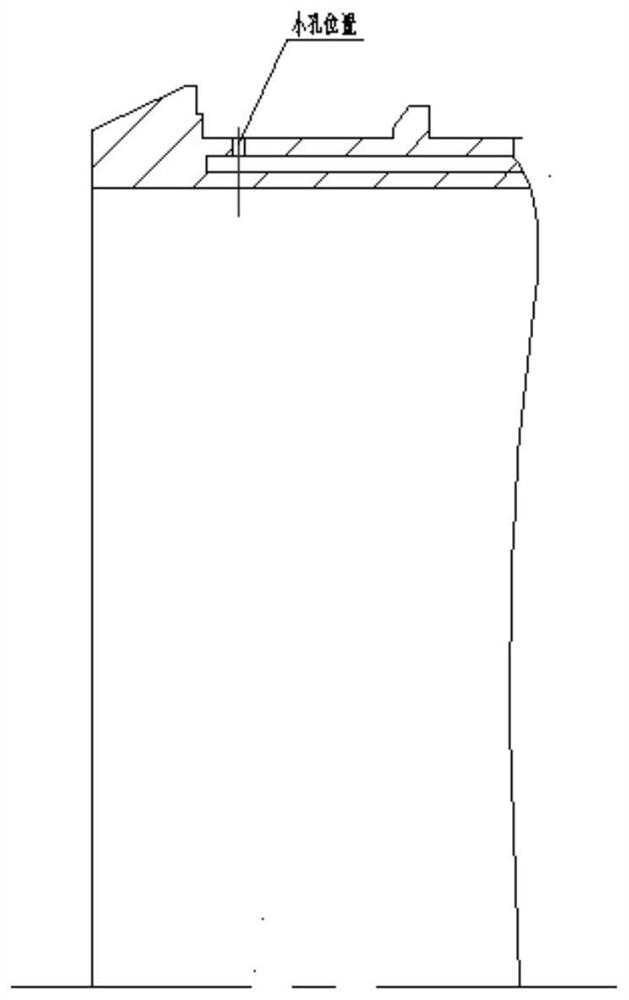
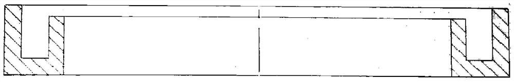
[0024] Among them, such as image 3 As shown, the surface of the product is an elliptical ring, and the positioning ring 3-1 is an elliptical ring (an annular structure consistent with the shape of the product), and an annular groove is processed on one end surface of the product, so that the positioning ring 3-1 includes an inner ring and an outer ring positioning ring 3-1 The outer circumferential surface of the inner ring is aligned with the inner circular surface of the product, and the outer ring is provided with through holes corresponding to the throttle holes on the product surface. The positioning ring 3-1 is provided with a symmetrical center positioning line or an angular position positioning line. During assembly, the positioning line on the positioning ring 3-1 is aligned with the corresponding symmetrical c...

Embodiment 2

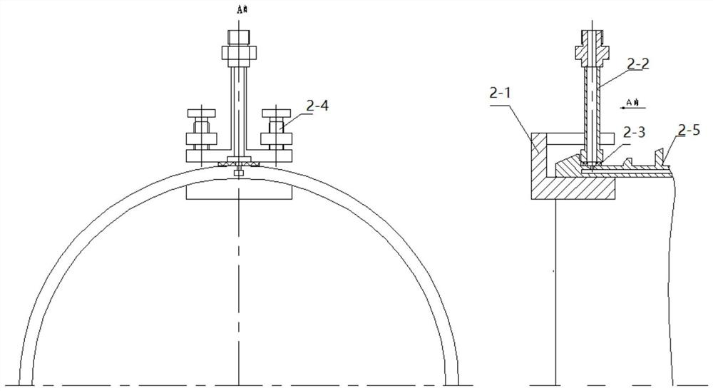
[0028] On the basis of embodiment 1, it also includes a slider 3-5 which is adjustable in position in the through hole of the outer ring of the positioning ring 3-1, the slider can move left and right in the through hole, and the center of the slider 3-5 is provided with Threaded hole, water inlet device 3-6 is screwed in the threaded hole of adjustable slide block 3-5 center by thread, as Figure 4 shown. The position-adjustable slide block 3-5 is set in the through hole of the outer ring, which is used to solve the problem that the water inlet device 3-6 and the orifice cannot be aligned due to processing errors of tooling and products. In this embodiment, the slider 3-5 is a T-shaped structure, which can slide slightly in the T-shaped groove on the outer ring of the positioning ring. If the orifice deviates during processing, the water inlet device can also be aligned with the orifice.


PUM


Abstract

The invention provides a flow rate calibration tool on an annular curved surface, which has a small limitation in the scope of use, can be applied to the flow rate calibration of the orifice on the complex curved surface, reduces the difficulty of clamping the orifice on the annular curved surface, and reduces the need for operation. Relying on the technical proficiency of personnel, reducing the time for repeated disassembly and assembly of tooling, and improving the efficiency of flow calibration at the same time. The flow calibration tooling of the present invention adopts an integral positioning ring and a detachable pressing ring to compress the water inlet device. , which reduces the difficulty of clamping the orifice on the annular surface, and can achieve simultaneous calibration of the porous position; the detachable compression ring has a simple structure, reduces tooling change time, and improves processing efficiency.

Description

technical field [0001] The invention belongs to the technical field of flow calibration, and in particular relates to a circular curved surface flow calibration tool. Background technique [0002] The structural parts of the active cooling of the engine are complex, and there are many throttle holes distributed on the surface, and the surface is generally a circular ring, an elliptical ring, and a special-shaped structure. The diameter of the orifice is generally below Φ0.8mm, see the location figure 1 , it is necessary to calibrate the flow rate of the orifice. Flow calibration requires water to enter from the orifice and water to exit from the cooling channel at the other end. Under a certain pressure, it is necessary to measure whether the flow per minute of a single orifice meets the index requirements proposed by the design. A single orifice cannot be directly connected to the flow table for flow calibration, and a special device must be designed to feed water from th...

Claims


Application Information

Patent Timeline
Patent Type & Authority Patents(China)
IPC IPC(8): B25B11/00
CPCB25B11/00
Inventor 麻丽红王勇杰王永飞刘月萍赵颖颖苏云玲
Owner BEIJING POWER MACHINERY INST
Why Eureka
Try Eureka