Plane display screen examination device

A technology for inspection devices and display screens, applied in the directions of loading/unloading, transportation and packaging, conveyor objects, etc., can solve problems such as damage to glass display screens, occupation, and complex structure of drive devices

Active Publication Date: 2009-07-22
DE&T
View PDF5 Cites 0 Cited by
  • Summary
  • Abstract
  • Description
  • Claims
  • Application Information

AI Technical Summary

Problems solved by technology

As a result, many problems are caused: due to the existence of the recoil force, the display screen conveying part 930 cannot accurately rotate the display screen P to a desired angle; and vibration and noise due to the meshing of the gears
In addition, there is such a problem that an additional shock-relieving brake is required to absorb the shock force generated when the display screen conveying unit 300 stops moving, and to prevent the frame 932 from turning over.
[0015] Because the carrier of the display screen transmission part 920, that is, the carrier that loads the display screen P onto the display screen inspection part 910 and unloads the display screen P from the display screen inspection part 910, is driven by a driver arranged under the carrier. While the glass display may be damaged during operation, fragments of the display will fall between the pulleys and the timing belt, both of which are the drive units, causing mechanical problems and abnormal operation
In addition, the driving device includes a motor, a plurality of pulleys, and a timing belt, so that the structure of the driving device becomes very complicated and takes up a lot of space
[0016] Since the data detector 913 and the grid detector 915 of the display screen inspection part 910 for inspecting the electronic defect of the display screen P are all installed on the platform 933, it is inconvenient to perform inspections on the data screen for inspection of display screens having different sizes. Additional adapters set on board and grid holder

Method used


Image

  • Plane display screen examination device
  • Plane display screen examination device
  • Plane display screen examination device

Examples


Embodiment Construction

[0039] Hereinafter, preferred embodiments of the present invention will be described in detail with reference to the accompanying drawings.

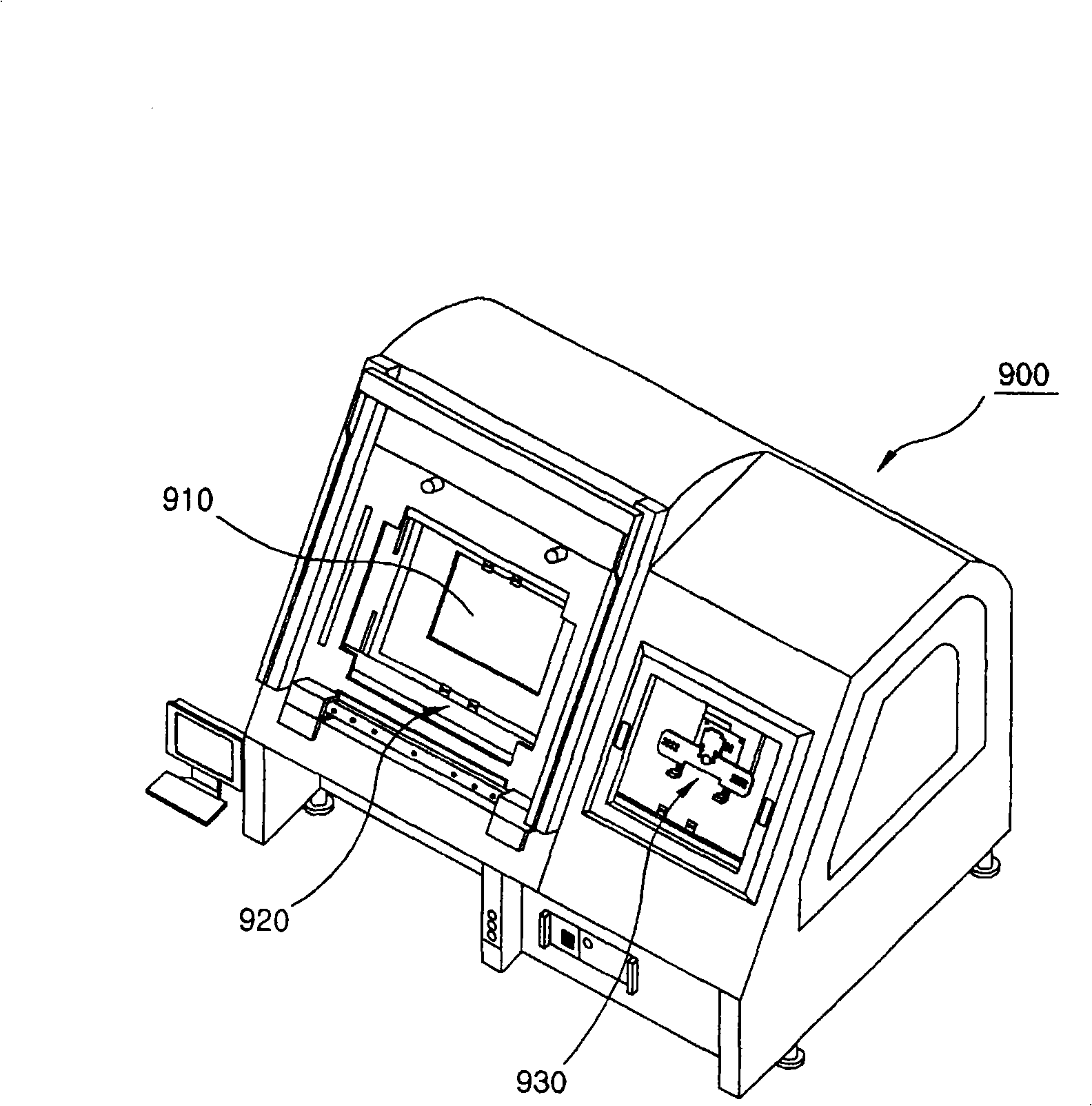
[0040] According to what will be described below, an inspection device according to the present invention also includes: a display screen inspection part, which checks electronic defects of the display screen by applying electric energy to the display screen; a display screen transfer part, which loads the display screen to the display screen On, or unloading, the display screen from the display screen inspection part; and a display screen transfer part, which transfers the display screen to the display screen transfer part.

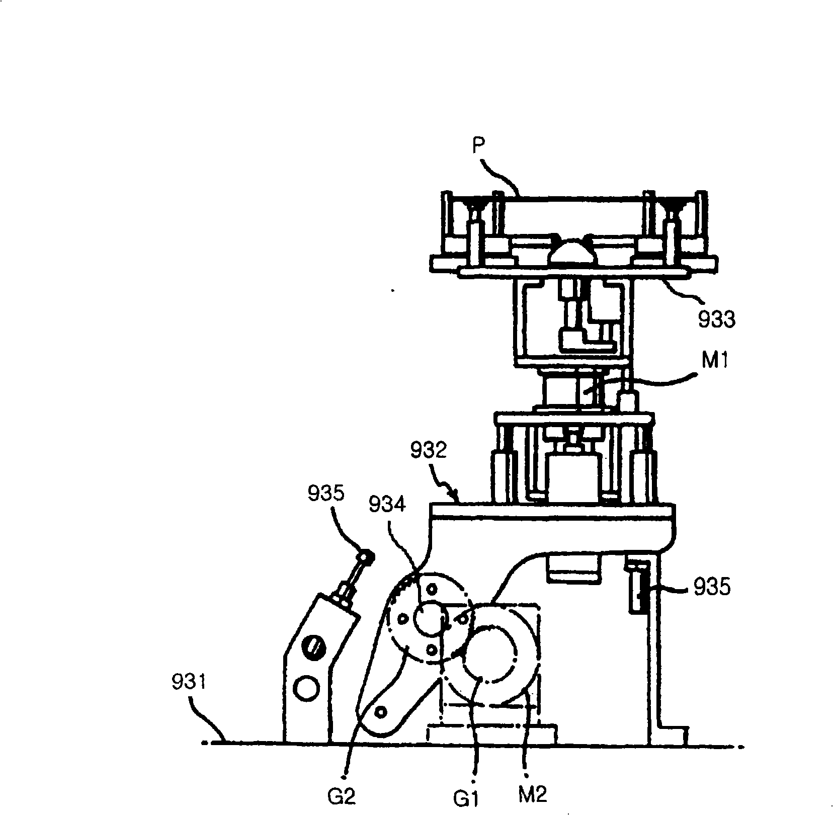
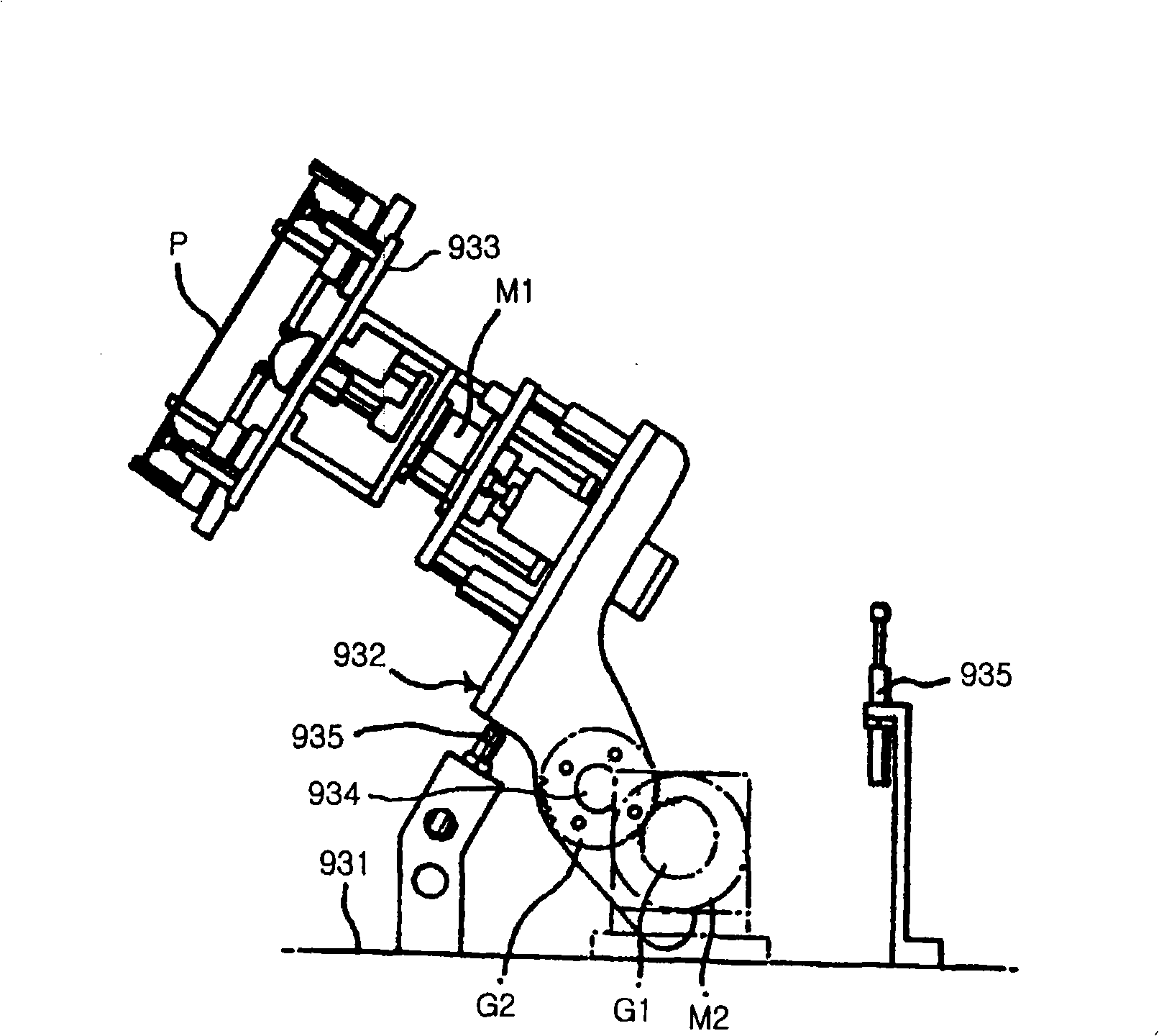
[0041] Figure 7 A perspective view of the display screen conveying part of the inspection device according to the invention is shown. refer to Figure 7 , the display screen conveying part includes: a frame 20, which is arranged on the base 10, and rotates around hinge shafts 21 on both sides of the frame 20; an...


PUM


Abstract

A flat display screen inspection device, comprising: a display screen inspection part for checking electronic defects of a display screen by applying electric energy to the display screen; a display screen transmission part for loading or unloading a display screen; and a display screen conveying part for transporting the display screen to the display transfer part. The inspection device is designed to minimize the recoil force generated during the rotation of the frame, and to allow the frame to rotate at a reduced speed when the rotation starts or stops, so that even for large screens mounted on the platform, it is possible to pass Limits impact and vibration for effective protection. In addition, the driving device is provided on the carrier, so that abnormal operation of the display screen transfer part caused by fragments of the glass display screen can be prevented. In addition, the data plate and grid holder can be removably mounted on the platform, making it easy to establish the position of the data detector and grid detector according to the size of the display screen, which will be used for changing the adapter and calibrating the detector The time and labor consumption is reduced to a minimum.

Description

technical field [0001] The present invention relates to a flat panel inspection device for inspecting appearance and electronic defects of flat panels such as LCD (Liquid Crystal Display), PDP (Plasma Display), EL (Electroluminescence Display) and the like. Background technique [0002] In general, a flat panel display is a new generation display device developed to replace a CRT (cathode ray tube) used for a television or a computer monitor. Demand for flat panel displays such as LCD, PDP, EL, etc. is rapidly increasing. [0003] In the process of manufacturing a display screen as described above, before integrating backlights, driving circuits, etc. separate from inferior products. [0004] figure 1 Shown is a perspective view of a conventional flat panel display inspection setup. refer to figure 1 , a traditional inspection device 900 is provided with: a display screen inspection part 910, which applies electric energy to the data lines and power lines arranged in ea...

Claims


Application Information

Patent Timeline
Patent Type & Authority Patents(China)
IPC IPC(8): G01N21/88B65G49/05B65G65/00
Inventor 林彩龙林在挺金泰镐权美禜姜栽焕
Owner DE&T
Why Eureka
Try Eureka