Circular braiding machine

A circular knitting machine and cam technology, applied in the field of circular knitting machines, can solve the problems of insufficient spring force, unstable rotor metal parts, jacquard effects, etc., and achieve the effects of halving the impact sound, stable action, and simplified clutch mechanism

Inactive Publication Date: 2009-07-29
ICHIKAWA IRON WORKS
View PDF7 Cites 2 Cited by
  • Summary
  • Abstract
  • Description
  • Claims
  • Application Information

AI Technical Summary

Problems solved by technology

[0007] However, the circular knitting machine of the new proposal operates when the solenoid is energized to pull the sliding shaft, so there is a problem that impact sounds are generated intermittently with the sliding of the solenoid core (plunger core)
In addition, when the solenoid pulls the core (plunger core) to push the cam follower back outside the action area of ​​the first cam, the fork is forced downward due to the action of the spring, but only the spring The elastic force of the rotor is not enough, and the function of each rotor metal part becomes unstable, which has a great impact on the jacquard problem

Method used


Image

  • Circular braiding machine
  • Circular braiding machine
  • Circular braiding machine

Examples


Embodiment Construction

[0016] Embodiments of the present invention will be described below with reference to the drawings.

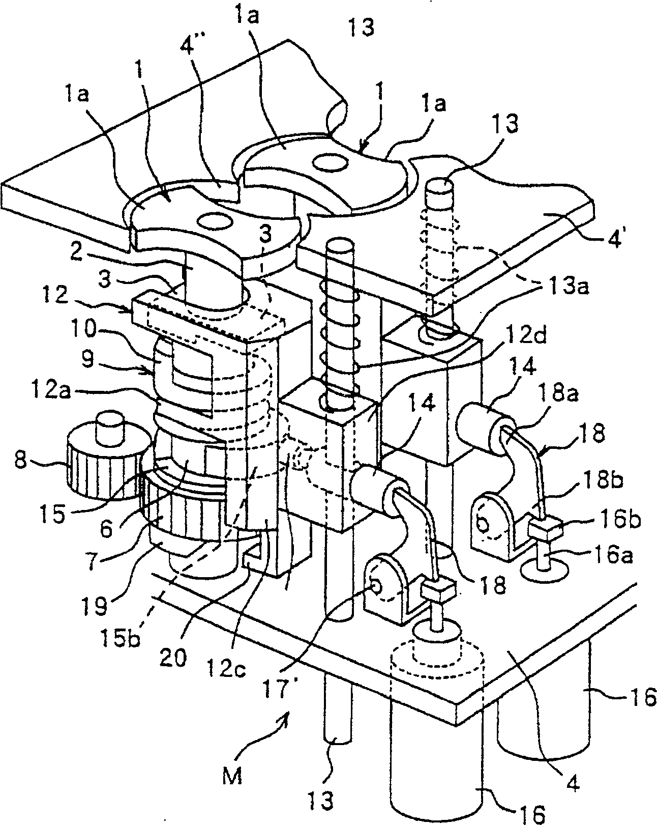
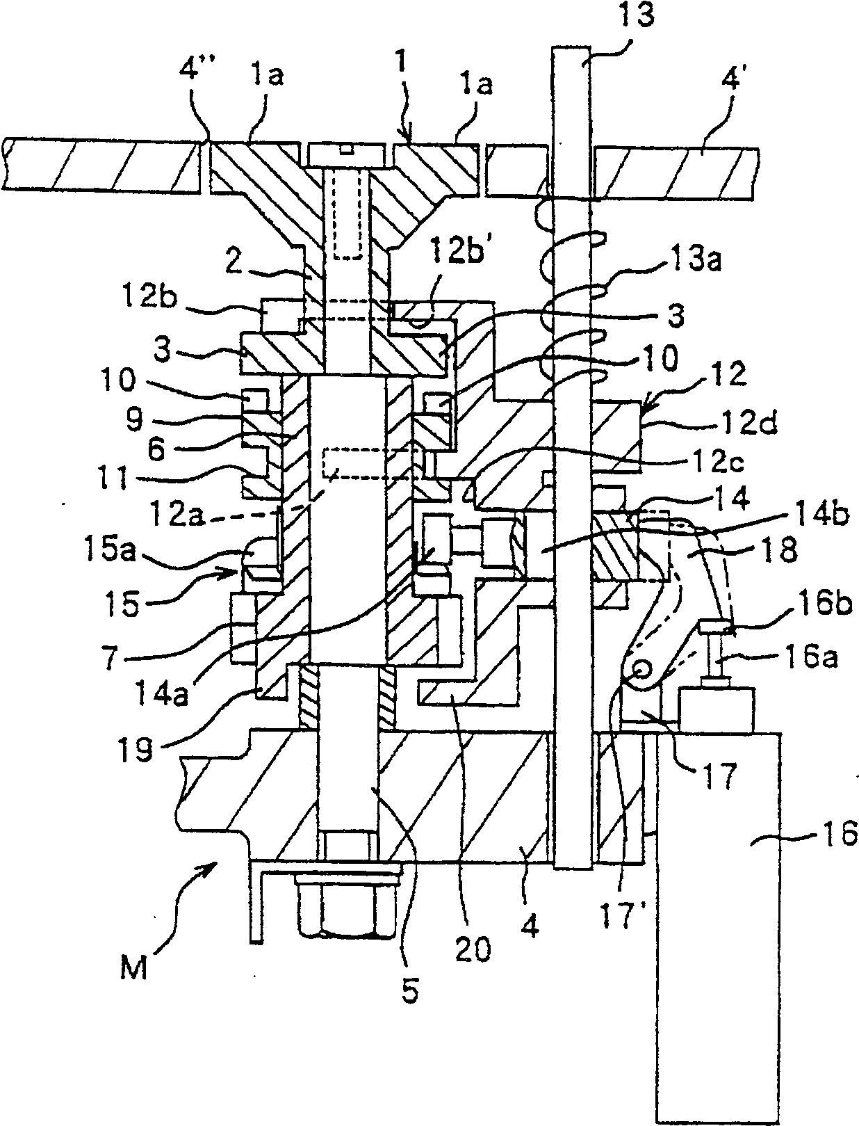
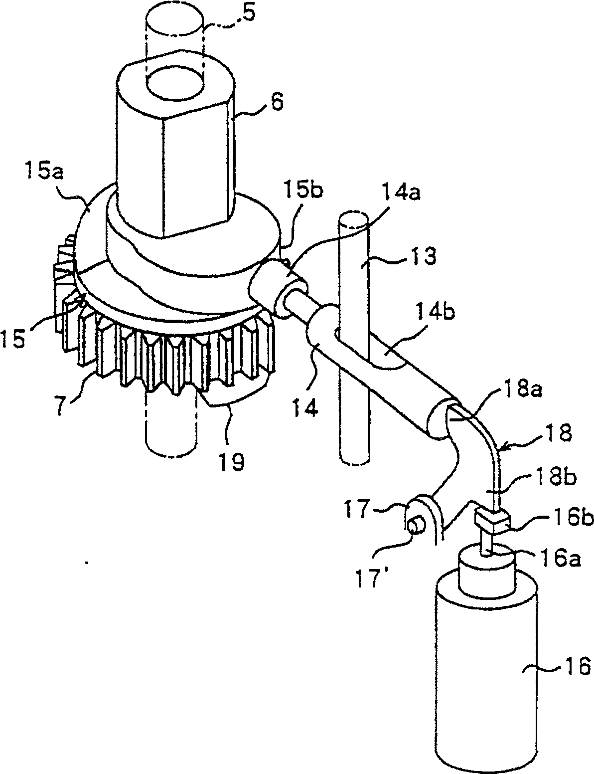
[0017] figure 1 It is an external perspective view of the main parts of the circular knitting machine according to the present invention. figure 2 It is a cross-sectional view when the slide shaft is pressed. image 3 It is a perspective view showing the relationship between the second cam and the slide shaft. Figure 4 It is a perspective view showing the relationship between the third cam and the fork.

[0018] In the figure, 1 is a rotor metal piece (ロ-タメタル), which is composed of the hollow shaft 2 and the fan-shaped parts 1a, 1a extending outward in a fan-shaped manner from the upper end of the hollow shaft 2, and the hollow shaft 2. The lower end is composed of claw pieces 3, 3 extending in the same direction as the fan-shaped parts 1a, 1a.

[0019] The rotor metal part 1 is rotatably loosely fitted in the horizontal direction on the upper part of a plurality of (64,...


PUM


Abstract

PURPOSE: A torsion lace machine is characterized by controlling applying an electric current to a solenoid, controlling travelling of a bobbin along a hole formed on an upper frame by a rotor metal and a rotor driving shaft, forming patterns precisely, forming a first cam and a second cam into one unit(a cam plate), unifying a third cam with a gear rotated with the rotor driving shaft and reducing a cost. CONSTITUTION: A torsion lace machine comprises: a clutch(9) connected when a rotor metal(1) and a rotor driving shaft(6) are moved upward and separated when the same are moved downward; a fork member(12) which is pushed by a spring(13a), supporting the clutch(9); a slide shaft(14) penetrating a back plate of the fork member(12) and being capable of sliding horizontally; a first cam operating a cam floor installed on an inner end of the slide shaft(14) to displace the fork member(12) upward through the slide shaft(14); a solenoid(16) pushing the slide shaft(14) to send the cam floor into an applying area of the first cam; a second cam(15b) pushing the slide shaft(14) to send the cam floor out of the applying area of the first cam; and a third cam reinforcing power of the spring(13a).

Description

technical field [0001] The present invention relates to a circular knitting machine (ト-ェョンレ-ス machine) that simplifies the structure of the clutch mechanism of the rotor metal part (ロ-tame-tal) and the rotor drive shaft, reduces the impact sound during clutching by half, and can accurately carry out jacquard. Background technique [0002] Circular knitting machines generally use the rotation (every 180 degrees) of multiple (64, 94, etc.) rotor metal parts arranged in the annular direction to make the bobbin rotate along the circumferential direction, and the The yarn pulled out from the bobbin is collected in the beating part arranged in the center of the ring to make a pattern (pattern). After beating, the yarn is sequentially wound on the winding drum through the nip roller. [0003] A plurality of rotor metal parts are overlapped and loosely fitted on the rotor drive shaft, which has been loosely fitted on the lower part of a predetermined number of fixed shafts that are ...

Claims


Application Information

Patent Timeline
Patent Type & Authority Patents(China)
IPC IPC(8): D04C3/24D04C3/00D04C5/00
CPCD04C1/06D04C3/38D04C5/00
Inventor 市川导宏市川武男
Owner ICHIKAWA IRON WORKS
Why Eureka
Try Eureka