Projector

A technology of a projector and a projection optical system, applied in the field of projectors, can solve problems such as difficulty in implementation

Inactive Publication Date: 2009-07-29
SEIKO EPSON CORP
View PDF13 Cites 0 Cited by
  • Summary
  • Abstract
  • Description
  • Claims
  • Application Information

AI Technical Summary

Problems solved by technology

[0011] However, in the case of a projector using a synthetic optical system having a multilayer film for blue reflection and a multilayer film for red reflection, the lighting device for illuminating liquid crystal panels of each color is subject to a structure in which green light is branched at the center. limits
That is, in this synthetic optical system, it is limited by the configuration of the optical path that makes the green image light straight and combines the blue or red image light from both sides, so it is difficult to realize, for example, that the light that is opposed to the green optical path is arranged on the green optical path. Chengchang's relay optical system projector
[0012] In addition, in the projector with the relay optical system arranged on the green optical path, although the multilayer film for blue or red reflection and the multilayer film for green reflection constitute the dichroic prism as the synthetic optical system, but for example, the green The image light at the border wavelength of blue forms a double image on the screen due to multiple reflections on the two multilayer films

Method used


Image

  • Projector
  • Projector
  • Projector

Examples


Embodiment 1

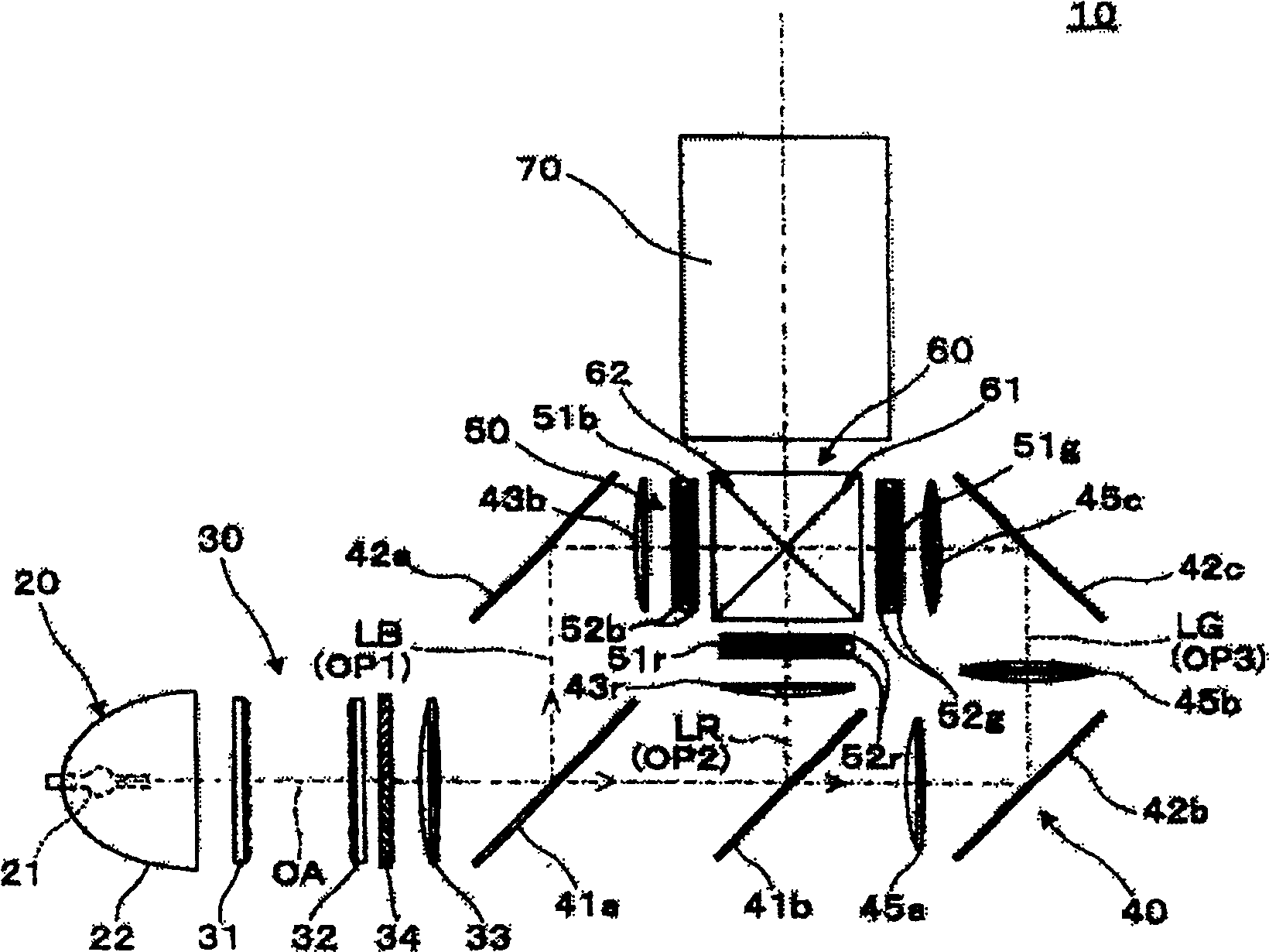
[0048] figure 1 It is a figure explaining the projector of Example 1 of this invention. This projector 10 has: a light source device 20 for emitting light source light, a homogenizing optical system 30 for homogenizing the illuminating light from the light source device 20, and dividing the illuminating light passing through the homogenizing optical system 30 into three colors of red, green and blue. The divided illumination system 40, the light modulation unit 50 illuminated by the illumination light of each color emitted from the divided illumination system 40, the cross dichroic prism 60 for synthesizing the modulated lights of each color from the light modulation unit 50, and the cross dichroic prism The image light of 60 is projected onto a projection lens 70 on a screen (not shown).

[0049] Among them, the light source device 20 has a lamp body 21 forming a substantially point-shaped light emitting portion, and a paraboloid-shaped concave mirror 22 for collimating ligh...

Embodiment 2

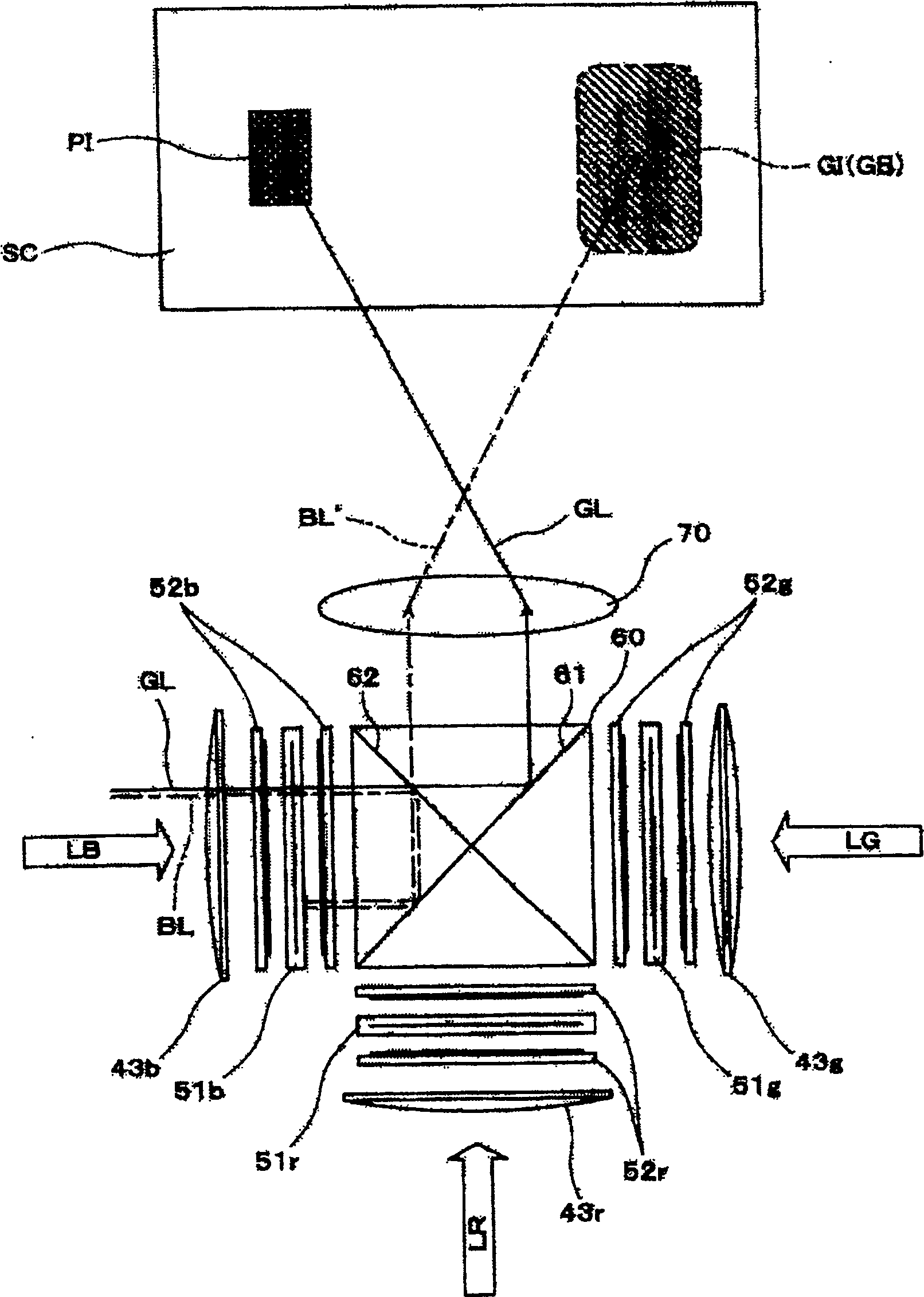
[0070] Figure 5 It is a figure explaining the projector of Example 2. The projector 110 is to be figure 1 The shown projector 10 of the first embodiment is a partially modified projector, and the parts not particularly described have the same structure as the projector 10 of the first embodiment, and the same reference numerals are assigned to the common parts and repetitions are omitted. illustrate.

[0071] The color separation optical system including the first and second dichroic mirrors 141a and 141b in the divided illumination system 40 separates the illumination light into three light beams of red light LR, green light LG and blue light LB. That is, the first dichroic mirror 141a reflects red light LR among the three colors of red, green, and blue, and transmits green light LG and blue light LB. In addition, the second dichroic mirror 141b reflects the blue light LB out of the incident green light LG and blue light LB, and transmits the green light LG.

[0072]In t...

Embodiment 3

[0081] Figure 8 It is a figure explaining the projector of Example 3. The projector 210 is to be figure 1 The shown projector 10 of the first embodiment is a partially modified projector, and the parts not particularly described have the same structure as the projector 10 of the first embodiment, and the same reference numerals are assigned to the common parts and repetitions are omitted. illustrate.

[0082] In the case of the projector 210 of the third embodiment, a bandpass filter 281 as an optical element is provided on the first optical path OP1 for guiding the blue light LB. In addition, in the illustrated example, although the bandpass filter 281 is provided between the reflection mirror 42a and the field lens 43b, the bandpass filter 281 may be arranged between the first dichroic mirror 41a and the cross dichroic mirror 41a. Any position on the optical path of the prism 260.

[0083] The cross dichroic prism 260 is a conventional cross dichroic prism corresponding...


PUM


Abstract

Provided is a projector capable of preventing double images from being formed due to multiple reflections of a synthetic optical system. In the projector (10), the reflection characteristics of a pair of dichroic films (61), (62) are prevented from repeating or overlapping. Thus, it is possible to prevent the boundary light (BL) of the blue light (LB) or green light (LG) incident on the cross dichroic prism (60) from being reflected twice by the dichroic films (61) and (62). And it becomes the return light which is incident on a liquid crystal panel (51g) etc. That is, it can be prevented that when the two dichroic films (61), (62) have overlapping reflection characteristics, the return light from them is reflected on the liquid crystal panel (51b) etc. A ghost image or the like is formed on the screen (SC).

Description

technical field [0001] The present invention relates to a projector for projecting images using a light modulation device such as a liquid crystal panel. Background technique [0002] As a conventional projector, there is an image light of each color emitted from a liquid crystal panel of each color illuminated by blue, red, and green illumination lights, and a pair of multilayer films for blue and red reflection are arranged in an X shape. A projector in which color synthesis is performed by a synthesis optical system (see Patent Documents 1, 2, 3, 4, and 5). In the above projector, the blue image light is reflected by the multilayer film for blue reflection, the red image light is reflected by the multilayer film for red reflection, and the green image light is reflected on the two multilayer films. Through the medium transmission, image light is superimposed, that is, color synthesis is performed (see patent documents 1, 2, 3, 4, and 5). [0003] Among them, in the firs...

Claims


Application Information

Patent Timeline
Patent Type & Authority Patents(China)
IPC IPC(8): G02B27/18G02F1/13H04N5/74H04N9/31
CPCH04N9/3197G02B27/1046H04N9/317H04N9/3105G02B27/145G02B27/149G02B27/142G03B21/00G03B21/14
Inventor 吉田宽治山川秀精唐泽穰儿坂口昌史
Owner SEIKO EPSON CORP
Why Eureka
Try Eureka