
Roller mill

A technology of roller mill and grinding table, which is applied in the field of roller mill, can solve the problems of large distance, achieve the effect of simple installation and disassembly, and reduce the overturning moment

Inactive Publication Date: 2009-08-12
F L SMIDTH & CO AS
View PDF4 Cites 0 Cited by
  • Summary
  • Abstract
  • Description
  • Claims
  • Application Information

AI Technical Summary

Problems solved by technology

The disadvantage of this roller mill is that, for example, radial forces act on the grinding surface, which subject the bearing design to a considerable tipping moment, which is proportional to the distance between the grinding surface plane and the bearing level, Whereas for known roller mills this distance is quite large

Method used


Image

  • Roller mill

Examples


Embodiment Construction

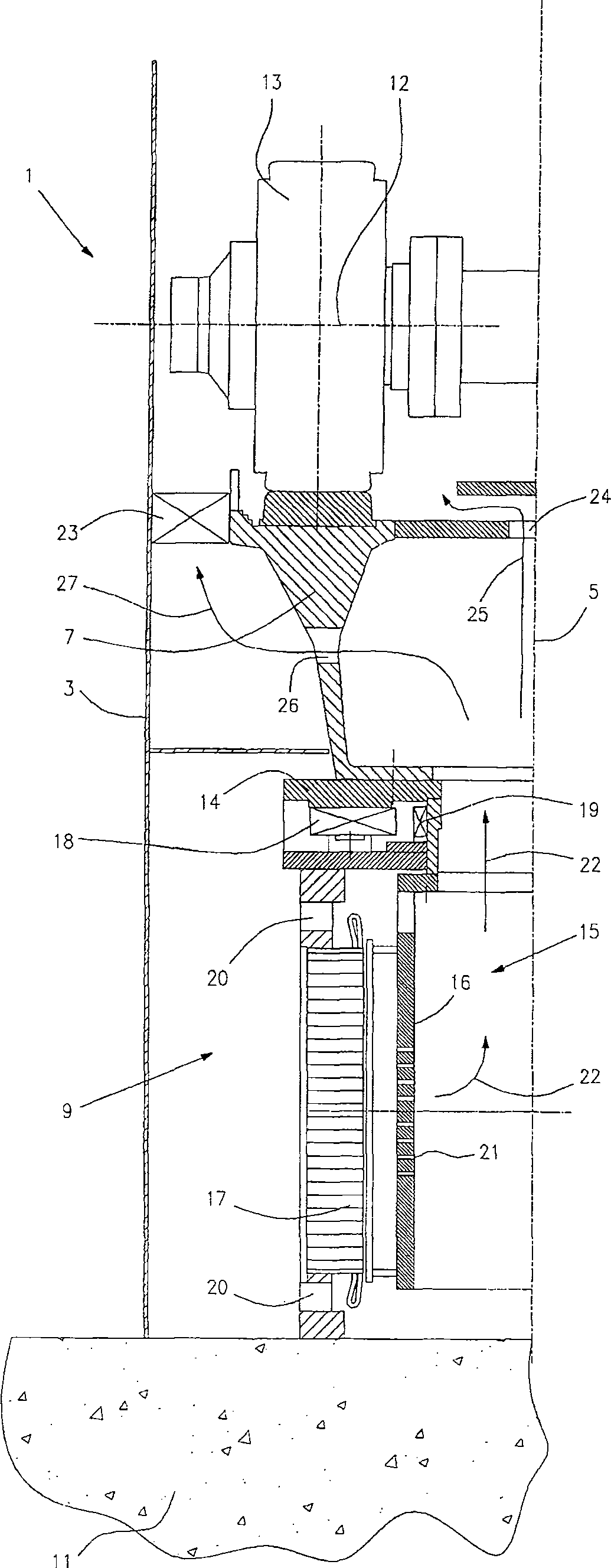
[0008] The figure shows a cross-sectional view of a roller mill 1 comprising: a housing 3 surrounding a grinding table 7 rotatable about a vertical axis 5 , said grinding table being supported by a machine base 11 via a support 9 at least one roller 13 rotatable about a substantially fixed axis 12 designed to interact with the grinding table 7 ; and an electric motor 15 comprising a rotor 16 firmly connected to the grinding table 7 and a stator 17 .

[0009] According to the invention, the stator 17 forms an integral part of the support 9, which also comprises: a slip ring 14, to which the grinding table 7 is fixed; a thrust bearing 18, when the grinding table 7 rotates during operation of the roller mill, A slip ring 14 moves on a thrust bearing 18 ; and a radial bearing 19 , which controls the radial movement of the grinding table 7 . Thus, the entire support 9 constituting the motor can be installed and replaced as a unit, while at the same time the unit tilting moment abso...


PUM


Abstract

A roller mill (1) for grinding granular materials such as cement raw materials, cement clinker and similar materials is described, said roller mill (1) comprising: a housing (3) surrounding a grinding table (7) , the grinding table (7) is rotatable about a vertical axis (5), said grinding table is supported by the machine bed (11) via a support (9); at least one roller (13), which is rotatable about a substantially fixed axis (12 ) rotates, said roller configured to interact with the grinding table (7); and a motor (15) comprising a rotor (16) firmly connected to the grinding table (7), and a stator (17). The roller mill is characterized in that the stator (17) constitutes an integral part of the support (9) of the grinding table (7), so that at least some of the load exerted by said at least one roller (13) on the grinding table (7) It is transmitted to the machine base (11) via the stator (17).

Description

technical field [0001] The present invention relates to a roller mill for grinding granular materials such as cement raw materials, cement clinker and similar materials, said roller mill comprising: a housing surrounding a grinding table rotatable about a vertical axis and passing through A stand is supported by the machine base; at least one roller, rotatable about a substantially fixed axis, configured to interact with the grinding table; and an electric motor, including a rotor rigidly connected to the grinding table, and a stator. Background technique [0002] Such a roller mill is known, for example, from UK Patent No. 1285102. With this known roller mill, a part of the outer circumference of the grinding table is configured as the rotor of the electric motor and is surrounded by a stator supported by the roller mill housing. A disadvantage of this known roller mill is that installation and maintenance are relatively complicated due to the need for magnetic / electrical ...

Claims


Application Information

Patent Timeline
Patent Type & Authority Patents(China)
IPC IPC(8): B02C4/42
CPCB02C15/006B02C15/007B02C15/003
Inventor 卢斯·彼得森
Owner F L SMIDTH & CO AS
Learn More