
Device for capturing palm print image based on photo optics

A technology of image acquisition and optical photography, which is applied in the directions of instruments, calculations, character and pattern recognition, etc., can solve problems such as unreasonable structural design of palmprint image acquisition equipment, unfavorable in-depth research on palmprint image acquisition methods, and affecting image acquisition quality , to achieve the effect of easy use, good design and convenient disassembly

Inactive Publication Date: 2009-08-12
PEKING UNIV
View PDF2 Cites 0 Cited by
  • Summary
  • Abstract
  • Description
  • Claims
  • Application Information

AI Technical Summary

Problems solved by technology

The research on online palmprint image acquisition method (including the design of acquisition equipment and auxiliary software) is a key issue in palmprint recognition. Among them, the palmprint image acquisition method based on optical photography has not yet had a satisfactory solution, which affects the performance of image acquisition equipment. Many factors, including light source (type, color, light intensity distribution), imaging system and palm positioning device, still need further research
In the existing acquisition equipment, these factors or most of them cannot be easily adjusted, which is not conducive to the in-depth study of the palmprint image acquisition method based on optical photography
As a result, the quality of image acquisition is affected, which directly leads to subsequent discrimination
And, the structure design of existing palmprint image acquisition equipment is unreasonable

Method used


Image

  • Device for capturing palm print image based on photo optics
  • Device for capturing palm print image based on photo optics
  • Device for capturing palm print image based on photo optics

Examples


Embodiment Construction

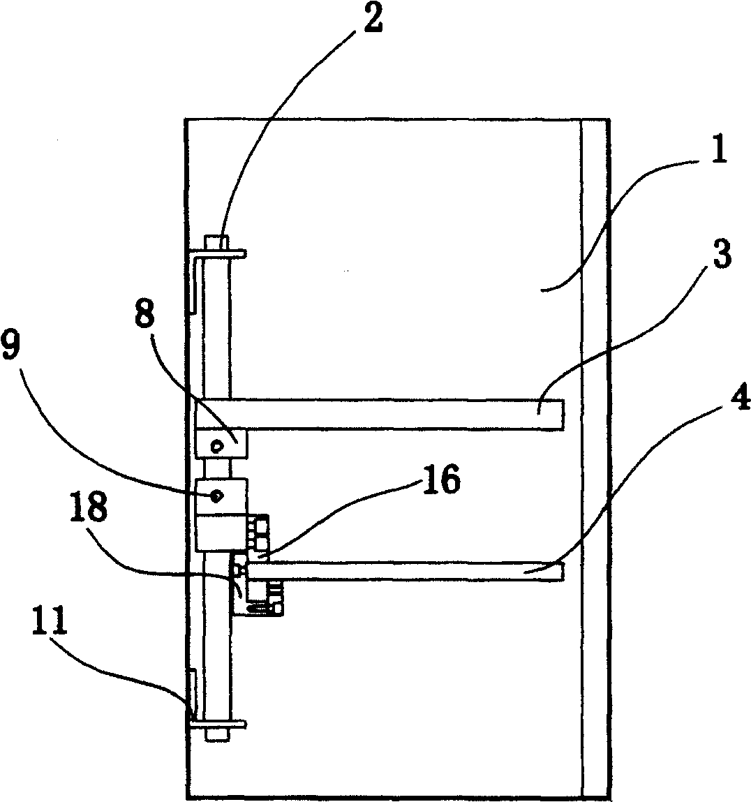
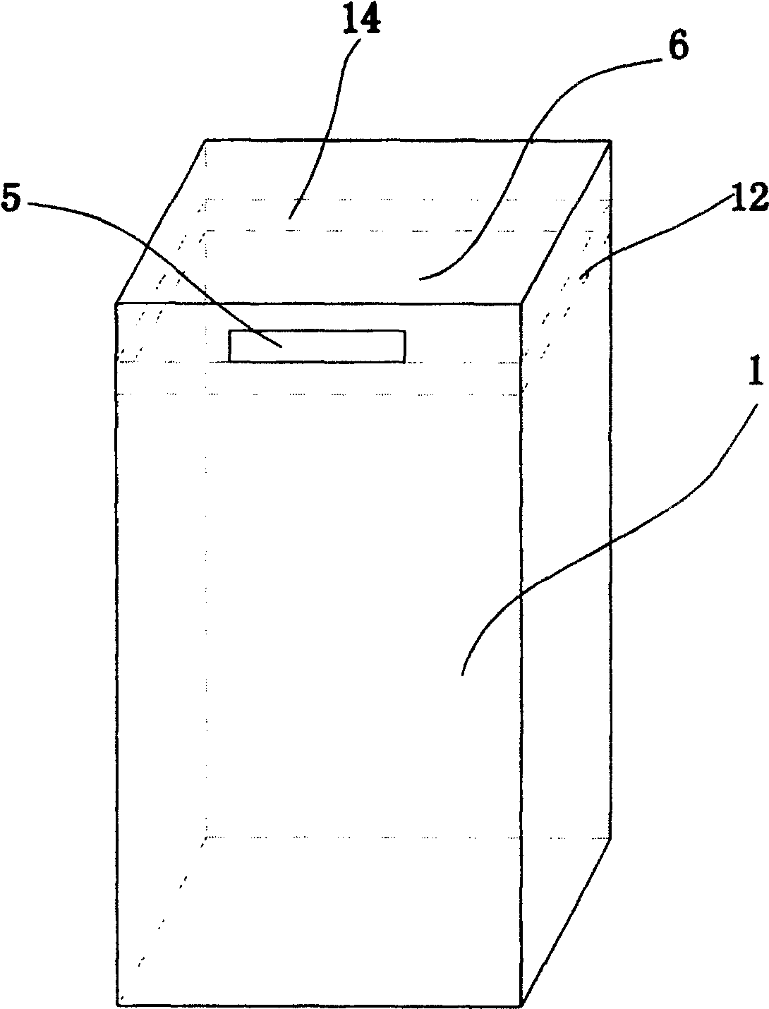
[0024] Such as figure 1 , 2 As shown, the present invention includes a casing 1, a positioning rod 2 vertically fixed in the casing, a light source bracket 3 and a camera bracket 4, a palm inlet 5 is opened on the side wall of the upper part of the casing 1, and a palm inlet 5 is arranged on the lower edge of the inlet 5. With support plate 6 ( figure 2 Dotted line part), the supporting plate 6 center is provided with the hole exposed for the center of the palm, the positioning bar 2 is provided with two sliders 8, and the light source bracket 3 and the camera bracket 4 are respectively connected on the slider 8. The casing 1 of the present invention is a substantially closed cubic structure. It can also take other structural forms.

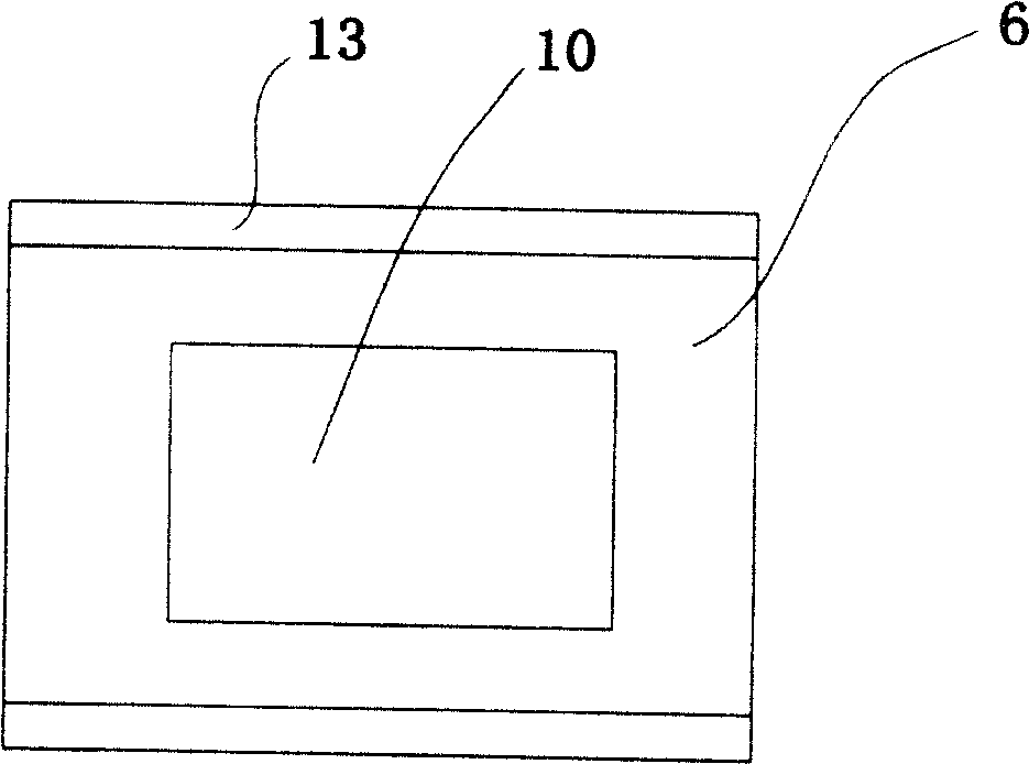
[0025] Such as figure 2 , 3 As shown, the support plate 6 is a rectangular plate with a hole 10 in the center, which is located at the lower edge of the entrance 5 . The two walls of the casing 1 are provided with slots 12 , and the two s...


PUM


Abstract

The invention discloses a palmprint image acquisition device based on optical photography, which includes a casing, a positioning rod vertically fixed in the casing, a light source bracket and a camera bracket, and a palm entrance is opened on the side wall of the upper part of the casing. The lower edge of the entrance is provided with a support plate, and the center of the support plate is provided with a hole for exposing the palm surface. The positioning rod is provided with two sliders that can be fixed on the positioning rod. The light source bracket and the camera bracket are connected to the sliders respectively. In the present invention, two sliders are arranged on the positioning rod, the light source bracket and the camera bracket are fixed on the sliders, a multi-circle light source jack is arranged on the light source bracket, and the camera is slidably connected to the camera bracket. The invention can dynamically adjust the position of the camera and the light source to obtain the palm image meeting the requirements. The present invention can be used for the research on the angle between the light source, the palm and the camera, and the imaging effect when the palm is taken, so as to better design the present invention and be more beneficial to the use of the present invention.

Description

technical field [0001] The invention relates to a palmprint image acquisition device based on optical photography. Background technique [0002] As an emerging identification technology, biometric identification is one of the most promising high-tech in the world and belongs to the international frontier topic. Palmprint recognition is an important branch of biometric technology. [0003] In the palmprint recognition system used for identity verification, the acquisition of palmprint images is an important aspect, which directly affects the difficulty of subsequent processing and the effect of processing results, and then affects the recognition rate, robustness and performance of the system . Over the past few decades, there have been patents for palmprint image acquisition devices and palmprint recognition based on different ideas. The research on online palmprint image acquisition method (including the design of acquisition equipment and auxiliary software) is a key is...

Claims


Application Information

Patent Timeline
Patent Type & Authority Patents(China)
IPC IPC(8): G06K9/20
Inventor 李文新赵蔚楠王国生许卓群
Owner PEKING UNIV
Learn More