Dynamic annular pressure control apparatus and method

A rock formation pressure and pressure technology, applied in the field of selective closed-loop boosting

Inactive Publication Date: 2009-09-02
PRAD RES & DEV LTD
View PDF9 Cites 0 Cited by
  • Summary
  • Abstract
  • Description
  • Claims
  • Application Information

AI Technical Summary

Problems solved by technology

As mentioned above, although additional weighting material can be added to the fluid, it is generally ineffective for dealing with gas kicks because it takes time to increase the fluid density in the wellbore

Method used


Image

  • Dynamic annular pressure control apparatus and method
  • Dynamic annular pressure control apparatus and method
  • Dynamic annular pressure control apparatus and method

Examples


Embodiment Construction

[0025] The present invention is used to achieve dynamic annular pressure control (DAPC) of a wellbore during drilling and insertion operations.

[0026] Structure of the preferred embodiment

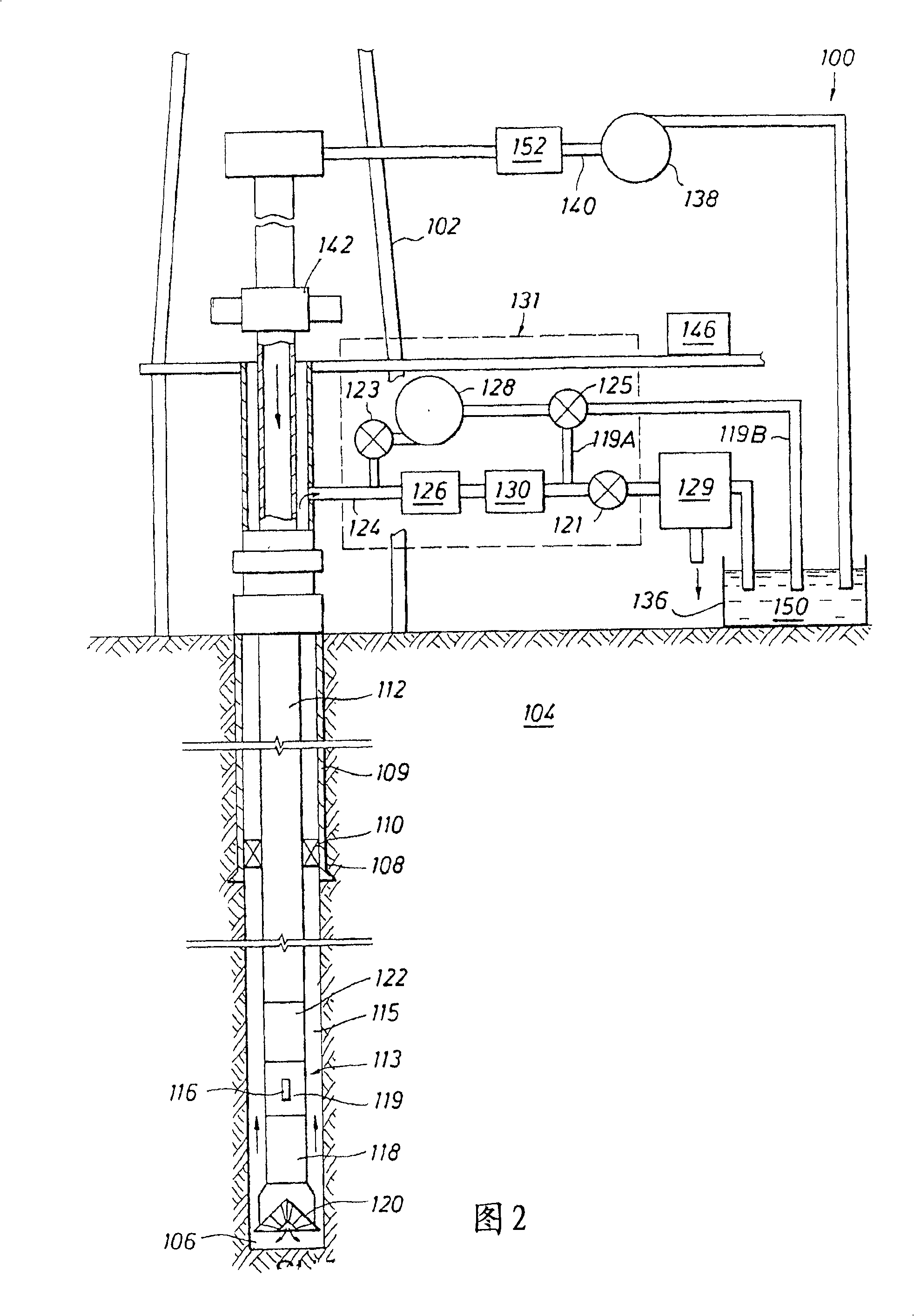
[0027] figure 2 A is a plan view showing a surface drilling system employing the present invention. It should be appreciated that offshore drilling systems may also employ the present invention. Drilling system 100 is shown including a drilling rig 102 for supporting drilling operations. For ease of illustration, many of the components used on the drilling rig 102 such as kelly, power tongs, slips, winches, and other equipment are not shown. Drilling rig 102 is used to support drilling and exploration operations in rock formation 104 . like figure 2As shown, the wellbore 106 has been partially drilled and the casing 108 has been set and glued 109 in place. In a preferred embodiment, a casing closing mechanism or downhole trim valve 110 is mounted on the casing 108 to selectivel...


PUM


Abstract

A system and method for controlling formation pressure during drilling of a subterranean formation utilizing a selective fluid back pressure system wherein fluid is pumped to a drilling fluid return system based on sensed wellbore pressure. A pressure monitoring system is also provided for: monitoring the detected wellbore pressure; modeling predicted wellbore pressure for further drilling; and controlling the fluid back pressure system.

Description

technical field [0001] The present invention relates to methods and systems for dynamically controlling wellbore annular pressure, and more particularly to a selective closed loop pressurization method for controlling wellbore pressure during drilling and other well completion operations. Background technique [0002] Both the exploration and production of hydrocarbons from subterranean formations ultimately require a method of reaching and extracting hydrocarbons from the formation. This is usually accomplished with a drill rig. In its simplest form it constitutes a land-based drilling rig for supporting a drill bit mounted at the end of a drill string and comprising a series of drilling tubulars. A fluid consisting of a base fluid (usually water or oil) and various additives is pumped down the drill string and out through the rotating drill bit. The fluid then flows back up the annular passage formed between the borehole wall and the drill bit, carrying away cuttings pro...

Claims


Application Information

Patent Timeline
Patent Type & Authority Patents(China)
IPC IPC(8): E21B21/08E21B44/00E21B21/10
CPCE21B44/00E21B21/08E21B21/106
Inventor 埃格伯特·J·范利特
Owner PRAD RES & DEV LTD
Why Eureka
Try Eureka