Casing structure and motor

A casing and structure technology, applied in the field of motors, can solve problems such as deterioration of waterproofness and electrical connection reliability, and achieve the effects of improving waterproofness, preventing poor electrical connection, and preventing water immersion

A casing and structure technology, applied in the field of motors, can solve problems such as deterioration of waterproofness and electrical connection reliability, and achieve the effects of improving waterproofness, preventing poor electrical connection, and preventing water immersion

CN100536283CActive Publication Date: 2009-09-02DENSO CORP

Image

  • Casing structure and motor
  • Casing structure and motor
  • Casing structure and motor

Examples


Embodiment Construction

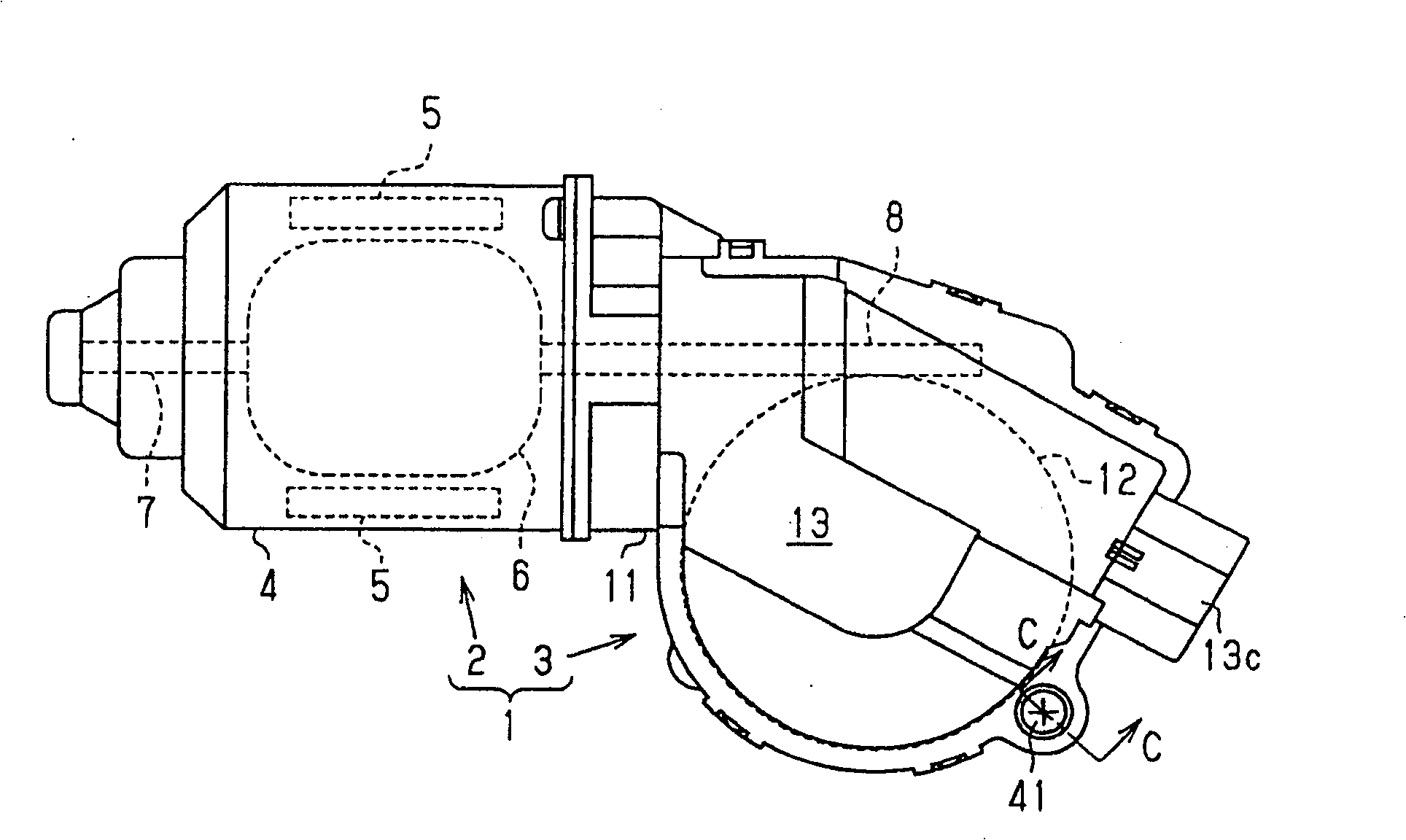
[0033] The following will be based on Figure 1 to Figure 15 An embodiment in which the present invention is embodied in a motor for a wiper device of a vehicle wiper device will be described.

[0034] Such as figure 1 As shown, a motor for a wiper device (hereinafter simply referred to as a motor) 1 has a motor main body 2 and a gear unit 3 . The motor main body 2 has a substantially bottomed cylindrical yoke housing (yoke housing) 4, a plurality of magnets 5 fixed to the inner peripheral surface of the yoke housing 4, and a rotor accommodated in the same yoke housing 4 ( Spinner) 6. The rotor 6 has a rotating shaft 7 , and a worm 8 is formed on the head end side of the rotating shaft 7 protruding from the opening of the yoke case 4 .

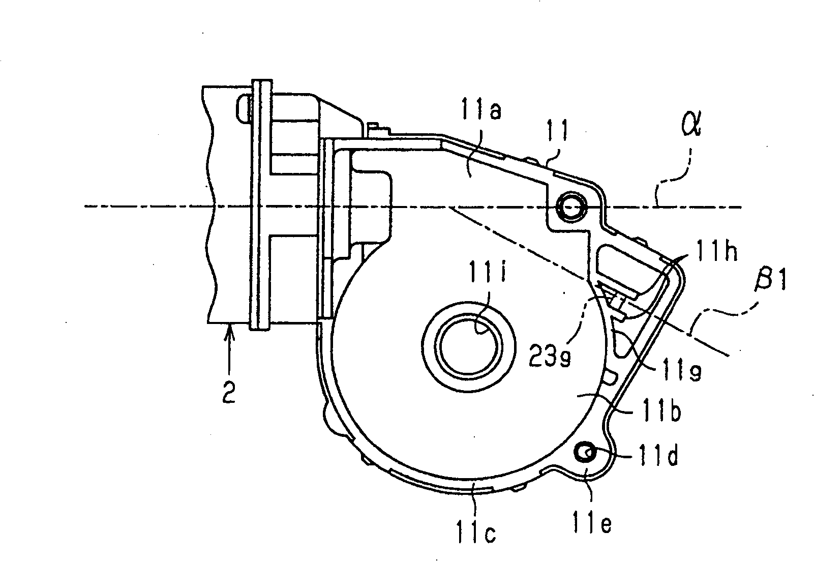
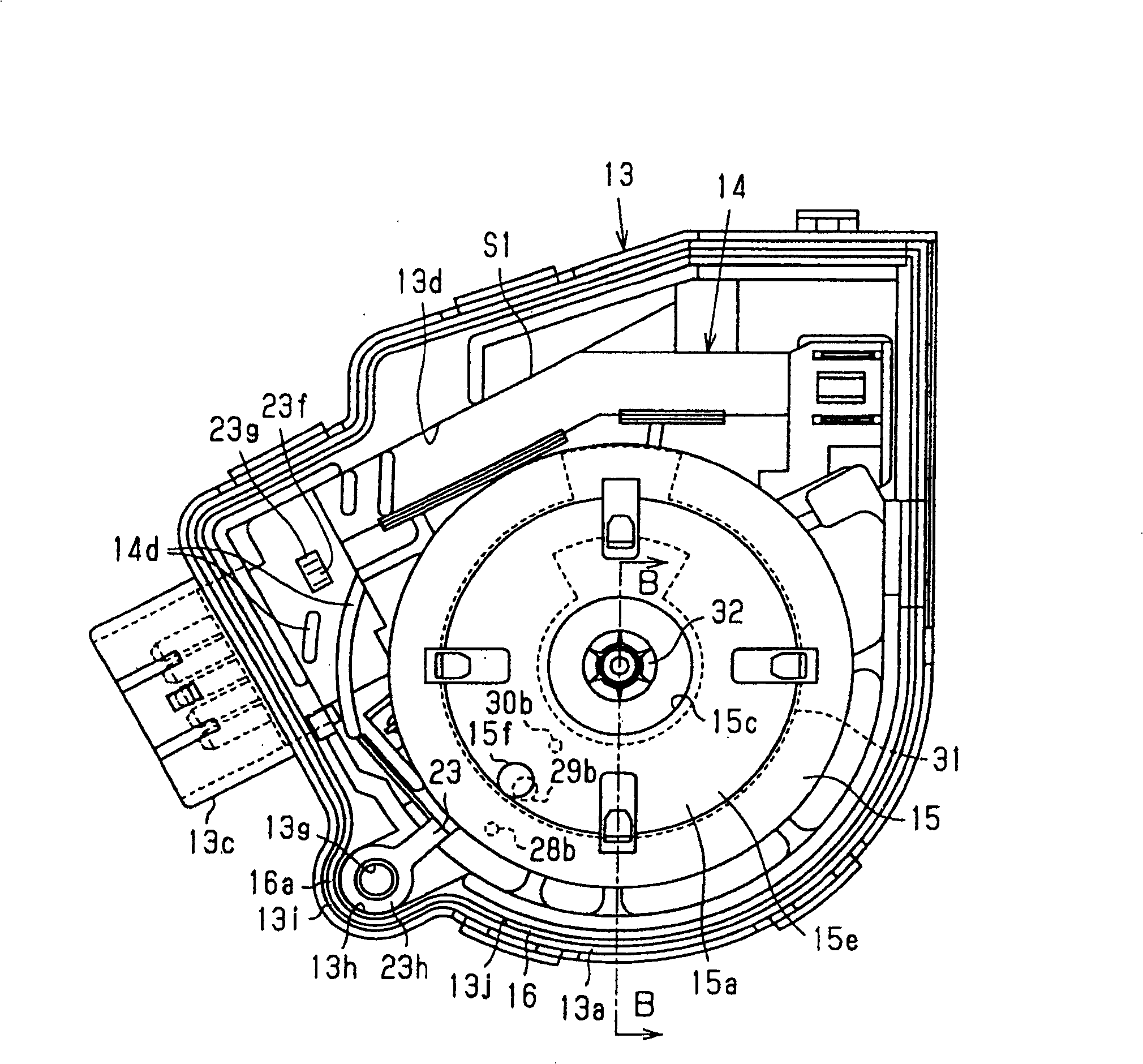
[0035] The gear part 3 has a case 11 as a gear case (refer to figure 2 ), worm gear 12 (refer to figure 1 ), the box cover 13 as a cover (refer to Figure 4 ), component board 14 (refer to Figure 6 ), rotating body 15 (refer to imag...


PUM


Abstract

A casing structure in which the side edge of the box body and the side edge (13a) of the cover (13) of the box are aligned, and are fixed by connecting holes (13g) inserted through them and bolts inserted into the holes , house electrical components including the first fixed contact terminal (23) inside them, and at the same time, configure the common connection portion (23h) of the first fixed contact terminal (23) in a manner surrounding the bolt, and use the box side edge It is clamped with the side edge part (13a) of the cover body. A box body side detour part (13i) bypassing the outside of the connection hole (13g) is formed on the cover body side edge part (13a) at the side edge part of the box body. The seal member (16) between the box-side edge portion and the lid-side edge portion (13a) has a seal-side detour (16a) passing through the box-side detour (13i) and the lid-side detour (13i). Therefore, waterproofness can be improved while ensuring the reliability of the electrical connection of the ground terminal.

Description

technical field [0001] The present invention relates to a case structure for accommodating electrical components including ground terminals and a motor using the case structure. Background technique [0002] Conventionally, a motor or the like used in a vehicle wiper device or the like has a motor main body and a gear unit. In the gear unit, electrical components such as gears and various terminals are housed inside the case and the cover that closes the opening of the case. In addition, as such a motor (casing structure), there is a design in which a part (common connection portion) of a ground terminal serving as an electrical component is sandwiched between both edge portions of the case body and the cover body (overlapped parts). In the connection part of the fitting surface), it is electrically connected with a box or a cover made of a conductive material (for example, JP-P-11-150910). Specifically, the box is fastened by a bolt that passes through a hole formed on on...

Claims


Application Information

Patent Timeline
02 Sep 2009
Publication
CN100536283C
IPC
H02K5/10
Inventors
村上精一