
Humidity regulating equipment

A technology of humidity regulation and equipment, applied in the direction of humidity control, control/regulation system, food testing, etc.

Inactive Publication Date: 2009-09-09
BUEHLER AG
View PDF6 Cites 1 Cited by
  • Summary
  • Abstract
  • Description
  • Claims
  • Application Information

AI Technical Summary

Problems solved by technology

However, the existing method of selecting grains and grain products by humidity measurement cannot be realized in the above-mentioned way.

Method used


Image

  • Humidity regulating equipment
  • Humidity regulating equipment
  • Humidity regulating equipment

Examples


Embodiment Construction

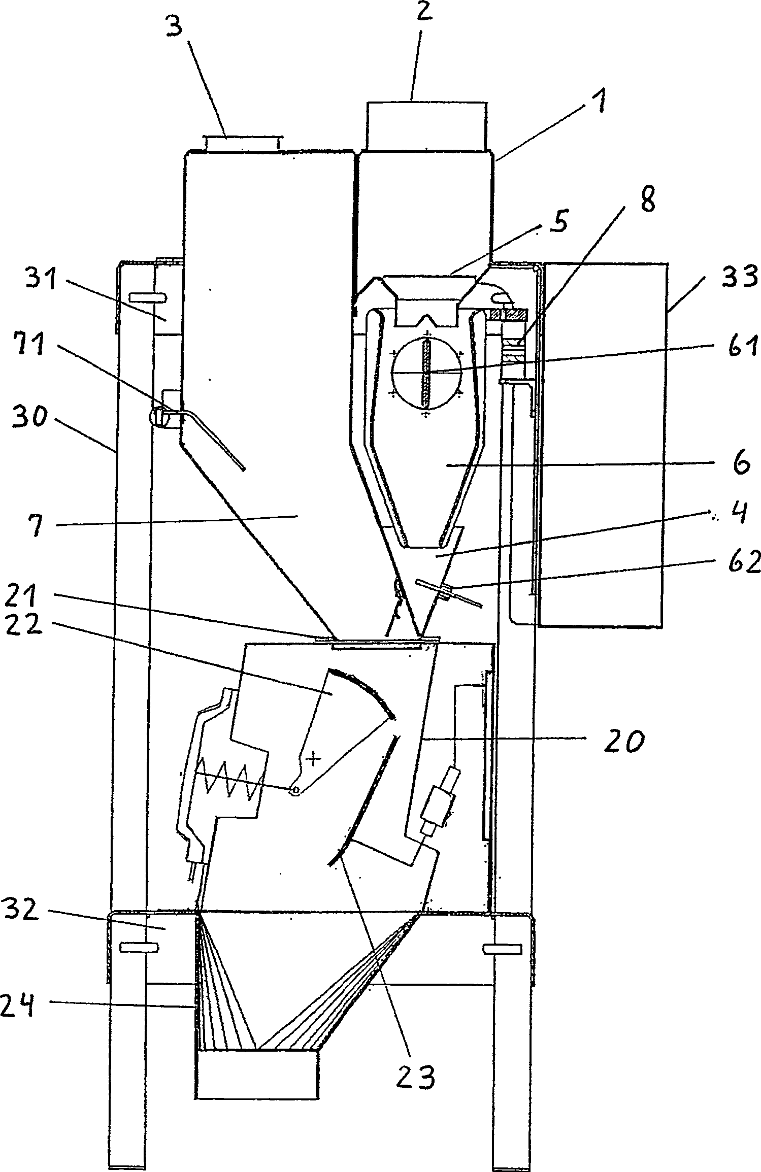
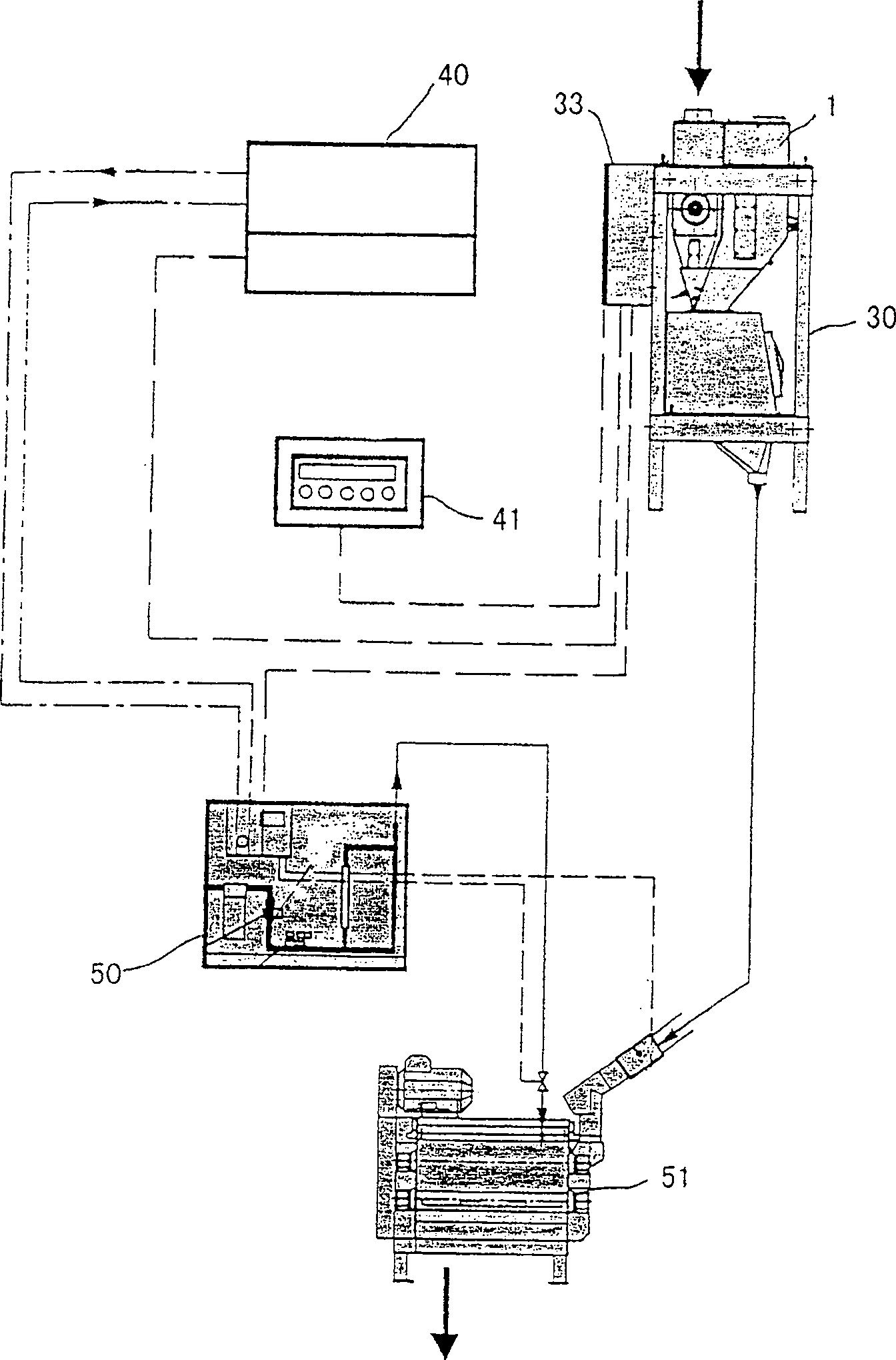
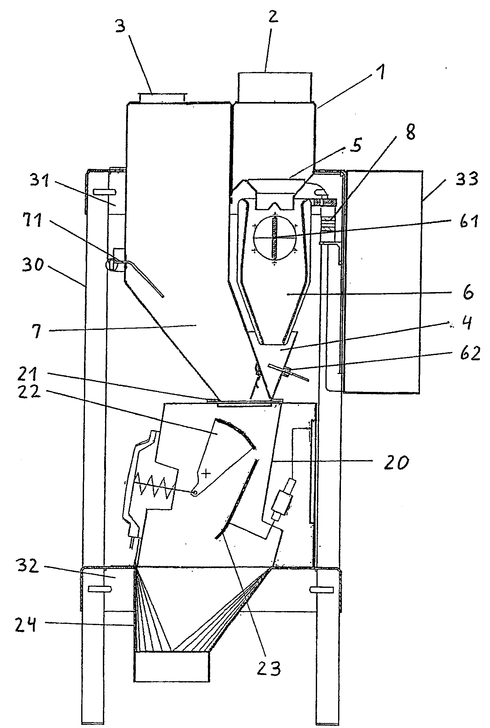
[0015] The humidistat comprises a housing 1 with an inlet 2 , a suction opening 3 and a discharge funnel 4 . Downstream from the inlet 2 are the feed tank 5 , the measuring path 6 and the main passage 7 in this order. The bulk material flow (grain) is damped and homogenized in the conveying device.

[0016] A microwave sensor 61 of the type described in patent document WO 96 / 38721 is arranged in the measuring path 6 , next to the measuring path 6 there is arranged a discharge funnel in which a temperature sensor 62 is arranged.

[0017] A material level sensor 71 is arranged in the main passage 7 for adjusting the material level of the bulk material flow introduced in the patent document EP-B-991473. The material level sensor 71 has a hinged mounting rod, which is set transversely or perpendicular to the flow direction of the bulk material and connected with a signal sensor.

[0018] The discharge funnel 4 is located above the supply port 21 of the flow regulator 20 . With ...


PUM


Abstract

The present invention relates to a humidity conditioning apparatus, in particular, to a humidity conditioning apparatus for continuously conditioning the humidity of bulk materials such as grains in milling equipment. The device comprises a measuring path (6) with a microwave sensor (61), which is designed as a three-plate line and is suspended on a weighing device separate from the main path of the bulk material. A flow controller (20) is located directly downstream of the device.

Description

field of invention [0001] The present invention relates to a humidity regulating device, in particular, the present invention relates to a device for continuously regulating the humidity of bulk materials such as grains located in a measuring pipeline by using a microwave sensor. Background technique [0002] Methods for continuously measuring the moisture content of bulk materials using capacitive sensors or microwaves are known. In patent document WO90 / 07110 a method of measuring the magnitude and phase of microwaves from bulk material and determining the moisture content of said bulk material is described. In order to generate the microwave field, an antenna is used which passes through the bulk material, preferably in the last part of the processing area, while simultaneously determining the temperature of the bulk material. However, the existing method of selecting grains and grain products by humidity measurement cannot be realized in the above-mentioned manner. [0...

Claims


Application Information

Patent Timeline
Patent Type & Authority Patents(China)
IPC IPC(8): G05D22/00G01N22/04G01N33/10G05D22/02
CPCG01N33/10G05D22/02G01N22/04
Inventor 罗曼·米勒瓦尔特·吕埃格克里斯托夫·考夫曼
Owner BUEHLER AG
Learn More