Supercharge Your Innovation With Domain-Expert AI Agents!

High-intensity discharge lamp of compact type with bulb holder

A high-intensity discharge lamp, compact technology, applied in the direction of discharge lamps, gas discharge lamp parts, discharge tubes, etc., can solve the safety problems of lamp reliability ballasts, distributed capacitance and inductance trigger pulse leakage, influence Lighting reliability and other issues, to achieve the effect of firm and reliable circuit boards and the entire structure, improved thermal shock and mechanical vibration resistance, and safe and reliable electrical performance

Active Publication Date: 2009-09-30
广东星光发展股份有限公司
View PDF3 Cites 0 Cited by
  • Summary
  • Abstract
  • Description
  • Claims
  • Application Information

AI Technical Summary

Problems solved by technology

But the disadvantage is that the distance between the trigger and the lamp head is long, the line is long, and the trigger pulse leaks more through the distributed capacitance and inductance between the leads, which not only reduces the pulse amplitude and widens the pulse width, which affects lighting, but also leaks the signal. Interference with surrounding electrical appliances
This trigger pulse may be coupled to the ballast circuit through the distributed capacitance and the inductance between the lines to cause interference, affect the normal operation of the ballast, make it out of control or even burn out
[0004] Another solution is to separate the trigger and the ballast, and connect them with wires, which can reduce the impact of the trigger signal on the ballast, but the distance between the trigger and the lamp is far away, and the trigger pulse leaks more. As mentioned earlier, this not only affects the lighting reliability, but also creates disturbances to the surroundings
[0005] The above several designs will cause the reliability of the lamp trigger and the safety of the ballast.

Method used


Image

  • High-intensity discharge lamp of compact type with bulb holder
  • High-intensity discharge lamp of compact type with bulb holder
  • High-intensity discharge lamp of compact type with bulb holder

Examples


Embodiment Construction

[0026] Below in conjunction with specific embodiment content of the present invention is described in further detail:

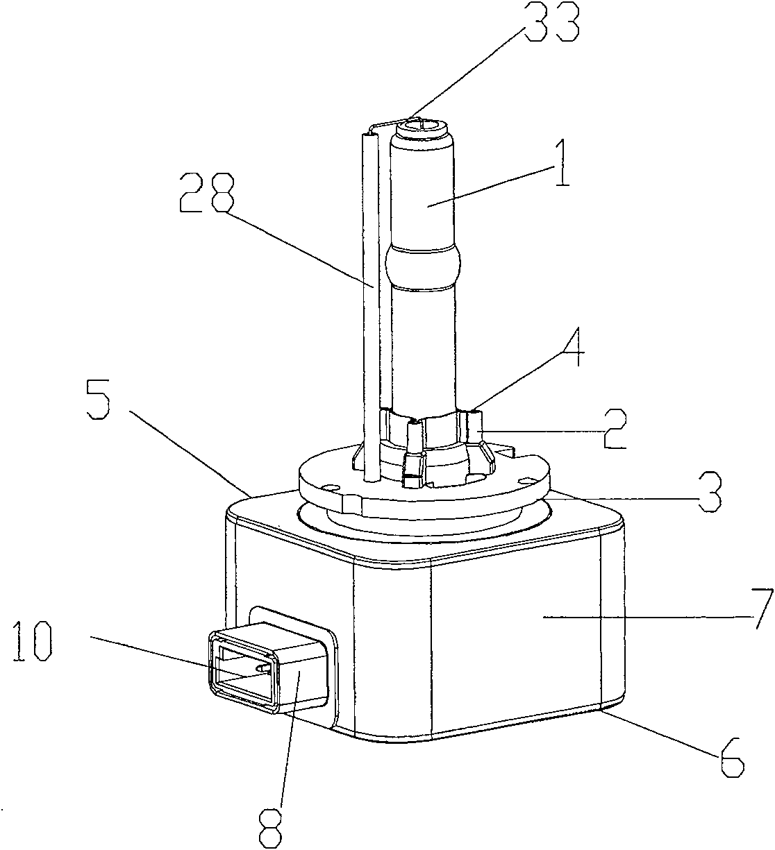
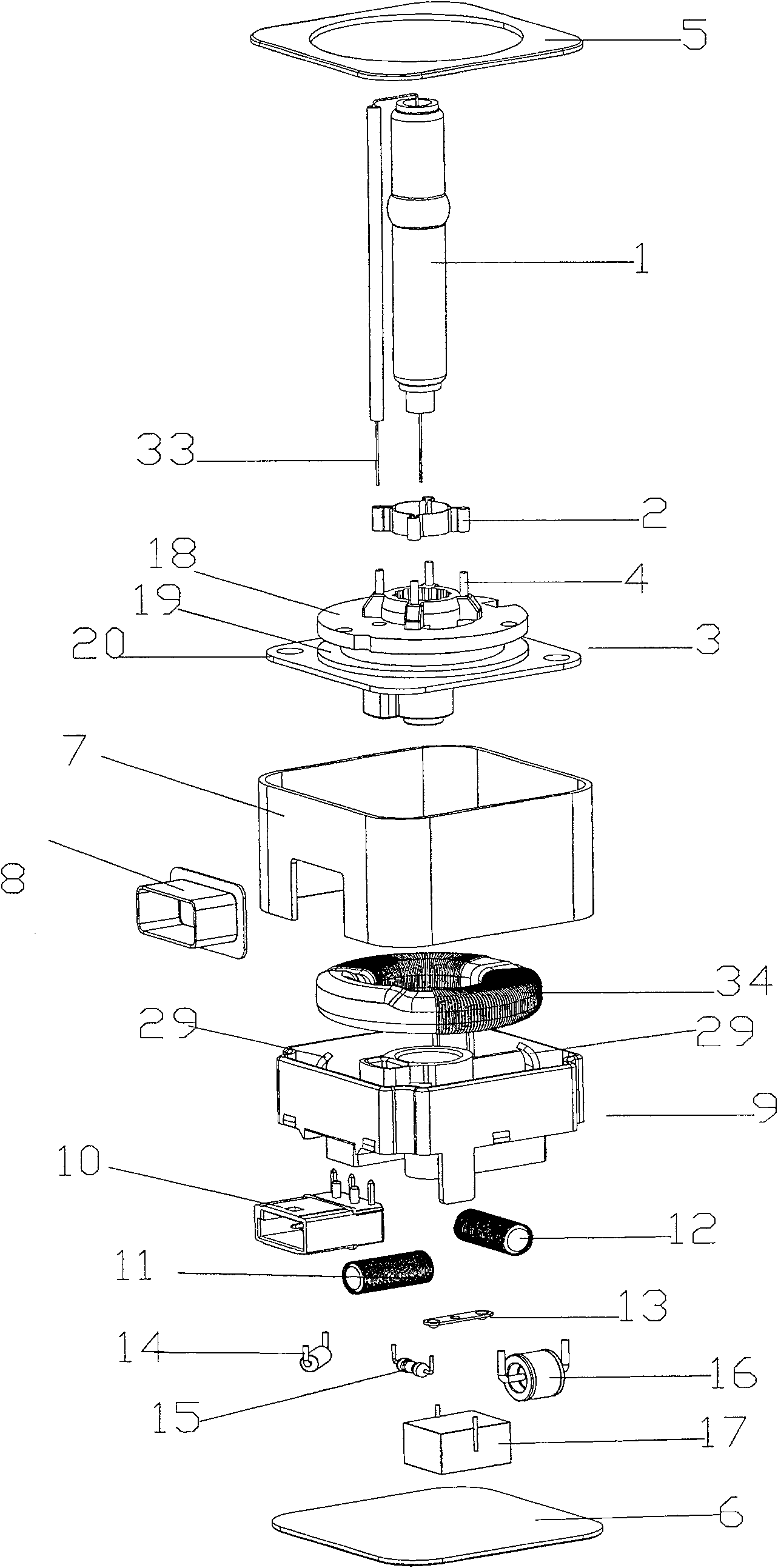
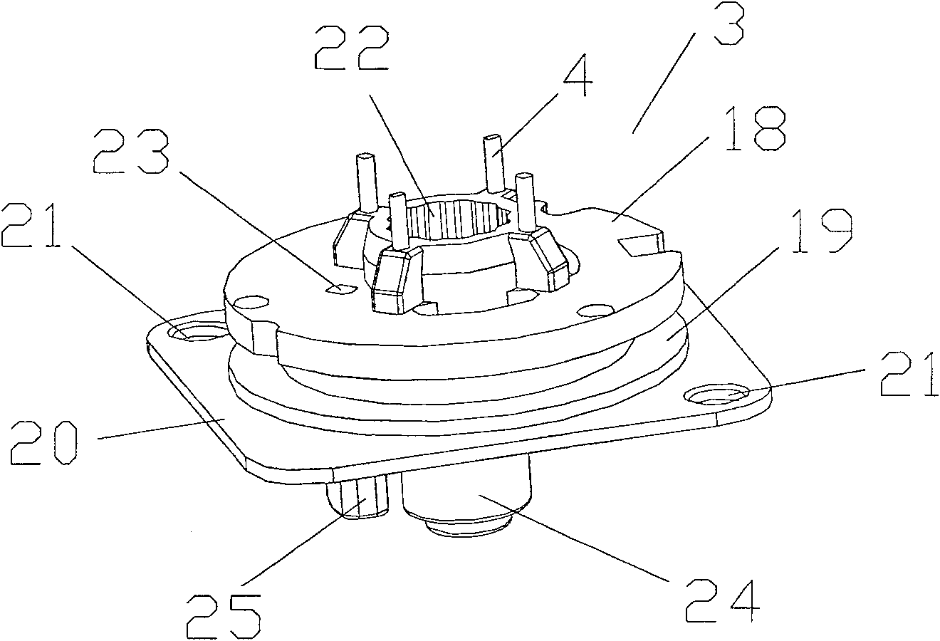
[0027] Such as figure 1 , 3 As shown, the present invention fixes the small high-intensity discharge lamp 1 in the discharge lamp tube fixing groove 22 of the lamp base carrier 3. The lamp base carrier 3 has a fixing pin rod 4 for fixing the bulb and embedded in the lamp base and is firmly welded on In addition to the lamp tube clamping ring 2 on the fixing pin, there is also a datum plane locating plate 18 and a datum reference plate 19 for positioning the lamp as a datum plane and matched with the lamp. The distance d set between the datum plane locating disc 18 and the datum reference disc 19 is exactly the width of the lamp tube fixing snap ring. Below the reference plate 19 is an insulating trigger module upper cover plate 20. There is a glue injection hole 21 on the trigger module upper cover plate 20. The center of the lamp cap is a lamp tube fixing ...


PUM


Abstract

The invention discloses a compact high-strength discharge lamp with a lamp head. A high-strength discharge lamp is fixed inside a lamp head carrier, an integrated trigger electrical module is arranged below the lamp head carrier and comprises a trigger circuit board, a trigger pulse transformer magnetic ring is compactly arranged in a magnetic ring fixing clip of the trigger circuit board, the other surface of the trigger circuit board is provided with a trigger coil isolation box for trigger coils to place; a power supply jack is electrically connected with the trigger circuit board; a module formed by the lamp head carrier and the trigger circuit board as well as all electronic components is electrically connected and then is sealed in a metal shielding box. The compact high-strength discharge lamp realizes that a trigger of a high air pressure discharge lamp is directly integrated in a lamp holder, which ensures that the produced voltage is directly connected between electrodes of a lamp tube, thereby reducing pulse energy loss, having good trigger performance, producing less interference to the external world, and particularly having small inference to ballasts further to cause the reliability of the ballasts to be greatly improved.

Description

technical field [0001] The invention relates to a compact high-intensity discharge lamp with a lamp base, in particular to a compact high-intensity discharge lamp with a trigger. Background technique [0002] A high-pressure discharge lamp with an inflation pressure of about 6 atmospheres in a cold state must be triggered by a high-voltage electric pulse to ignite the lamp. The pulse width is about 0.1us, and the peak voltage is above 20kv. Such a narrow high-voltage trigger pulse Harmonics contain very high-frequency high-frequency harmonics, which may radiate through space or couple with nearby metal substances or directly leak through lead coupling, which not only causes pulse energy leakage and reduces trigger reliability, but also may interfere with surrounding electrical appliances. Burn out the ballast. [0003] Usually this type of trigger is designed together with an electronic ballast, the power supply of the trigger is directly taken from the ballast, and the con...

Claims


Application Information

Patent Timeline
Patent Type & Authority Patents(China)
IPC IPC(8): H01J61/02H01J61/56H01J5/50H05B41/24
Inventor 杨正名高光义柴国生
Owner 广东星光发展股份有限公司
Features
  • R&D
  • Intellectual Property
  • Life Sciences
  • Materials
  • Tech Scout
  • Unparalleled Data Quality
  • Higher Quality Content
  • 60% Fewer Hallucinations
Learn More