Transmission circuit for generating modulating wave signal and communication equipment comprising the circuit

A technology of transmission circuit and modulation wave, which is applied in the field of transmission circuit and can solve the problems of high power consumption of transmission circuit

Inactive Publication Date: 2009-10-14
PANASONIC CORP
View PDF8 Cites 0 Cited by
  • Summary
  • Abstract
  • Description
  • Claims
  • Application Information

AI Technical Summary

Problems solved by technology

As a result, transmission circuits capable of broadband operation disadvantageously have high power consumption

Method used


Image

  • Transmission circuit for generating modulating wave signal and communication equipment comprising the circuit
  • Transmission circuit for generating modulating wave signal and communication equipment comprising the circuit
  • Transmission circuit for generating modulating wave signal and communication equipment comprising the circuit

Examples


no. 1 example

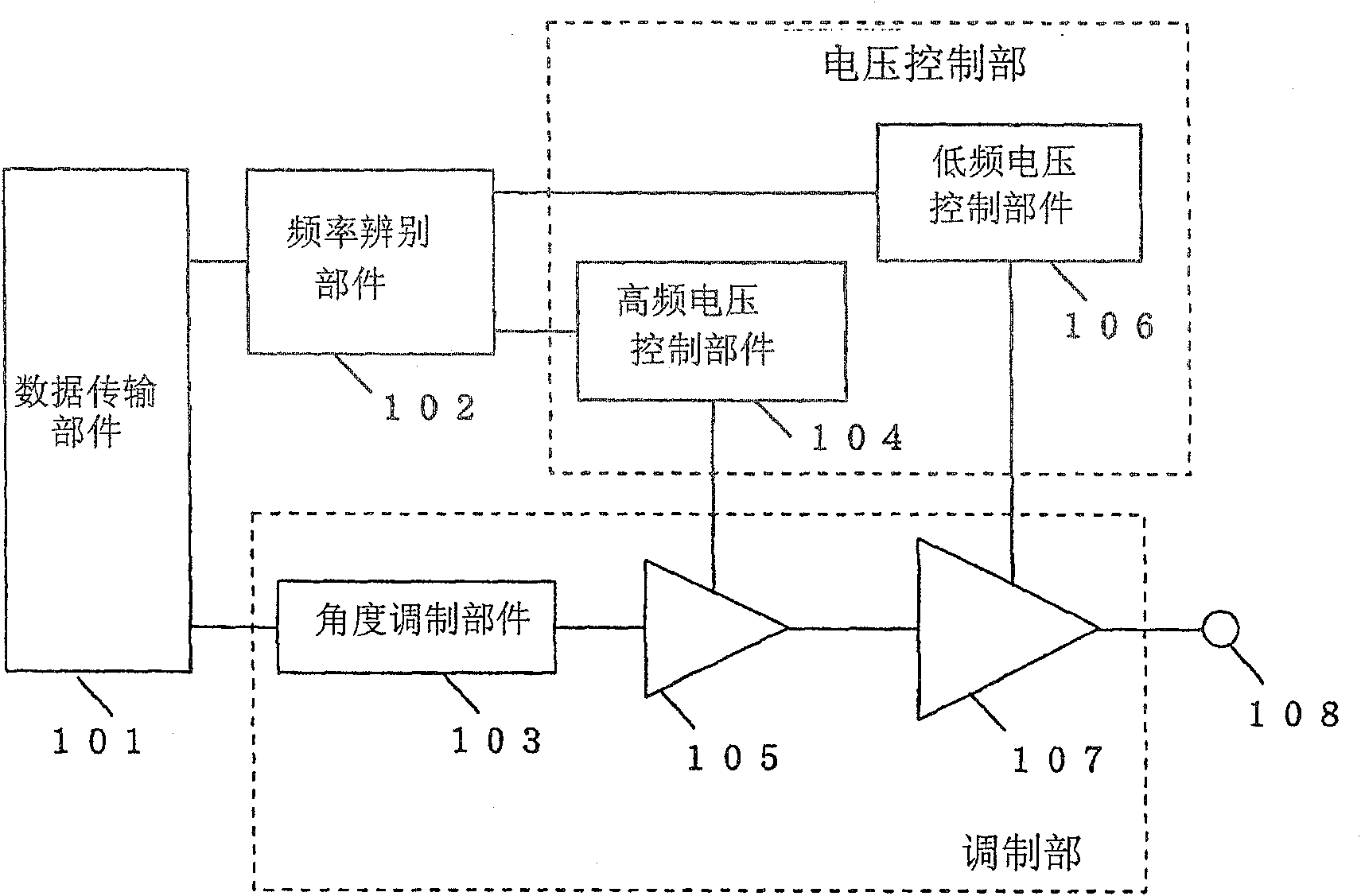
[0090] figure 2 is a block diagram showing an exemplary configuration of the transmission circuit 20 as described in Embodiment 1 of the present invention. refer to figure 2 The transmission circuit 20 includes a data generation unit 101, a frequency discrimination unit 102, an angle modulation unit 103, a high frequency voltage control unit 104, a low frequency voltage control unit 106, an amplitude modulation unit 105, an amplitude modulation unit 107 and an output terminal 108.

[0091] It is worth noting here that the high frequency voltage control part 104 and the low frequency voltage control part 106 may be combined into one voltage control part. The angle modulating part 103, the amplitude modulating part 105 and the amplitude modulating part 107 may be combined into one modulating part.

[0092] refer to figure 2 , the data generating section 101 generates a signal (amplitude signal) including an amplitude data component and a signal (phase signal) including a p...

Embodiment 2

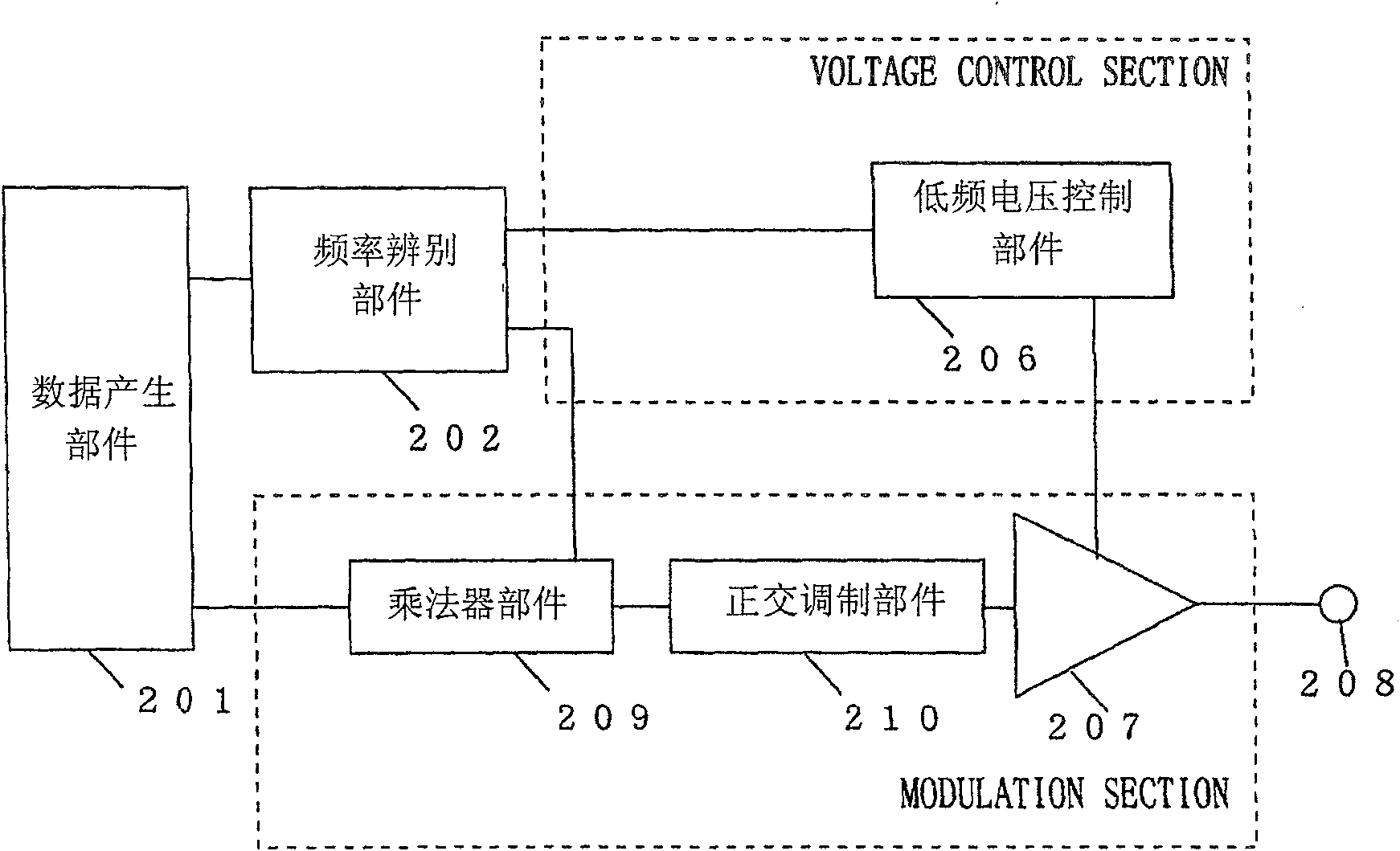
[0134] image 3 is a block diagram showing an exemplary structure of the transmission circuit 20 as described in Embodiment 2 of the present invention. The transmission circuit 20 of Embodiment 2 differs from that of Embodiment 1 in the following points. In Embodiment 2, the data generation unit 201 outputs quadrature signals instead of phase signals. In addition, the angle modulation section 103, the high-frequency voltage control section 104, and the amplitude modulation section 105 of Embodiment 1 are replaced with the multiplier section 209 and the quadrature modulation section 210 in Embodiment 2.

[0135] refer to image 3 , the transmission circuit 20 includes a data generation section 201 , a frequency discrimination section 202 , a multiplier section 209 , a quadrature modulation section 210 , a low frequency voltage control section 206 , an amplitude modulation section 207 and an output terminal 208 .

[0136] The data generation section 201 generates an amplitude...

Embodiment 3

[0158] Figure 5 is a block diagram showing an exemplary structure of the transmission circuit 20 as described in Embodiment 3 of the present invention. The transmission circuit 20 of Embodiment 3 is different from that of Embodiment 1 in that the high-frequency voltage control section 304 and the low-frequency voltage control section 306 are connected in series.

[0159] refer to Figure 5 , the transmission circuit 20 includes a data generation unit 301 , a frequency discrimination unit 302 , an angle modulation unit 303 , a high frequency voltage control unit 304 , a low frequency voltage control unit 306 , and amplitude modulation units 307 and 308 . It is worth noting here that these components are similar to those of Example 1 and will not be explained again.

[0160] The high frequency voltage control part 304 and the low frequency voltage control part 306 may be combined into one voltage control part. The angle modulation component 303 and the amplitude modulation c...


PUM


Abstract

A transmission circuit capable of transmitting a modulated wave signal modulated using polarization modulation over a broadband and providing low power consumption. The transmission circuit generates an amplitude signal and a phase signal based on the data to be transmitted, and separates the amplitude signal into a low-frequency amplitude signal and a high-frequency amplitude signal. The transmission circuit uses the high-frequency amplitude signal in the high-frequency voltage control part (104) and the amplitude modulation part (105) to amplitude-modulate the phase signal in the broadband, and uses the low-frequency voltage control part (106) and the amplitude modulation part (107) The low frequency amplitude signal is used to amplitude modulate the phase signal into low power consumption.

Description

technical field [0001] The present invention relates to transmission circuits for communication devices such as mobile phones, wireless LANs and the like. In particular, the invention relates to transmission circuits capable of low power consumption and broadband operation. Background technique [0002] Recently, mobile communication systems (such as mobile phones, wireless LANs, etc.) use broadband modulated signals in high-speed data transmission. Therefore, a communication device provided in a terminal needs to operate at broadband and consume low power. Communication equipment consumes a lot of power to amplify the output power of transmitted radio waves. Accordingly, such communication devices require a transmission circuit capable of operating at a wide band and amplifying output power with low power consumption. [0003] Traditionally, polar modulation is a known technique for operating transmission circuits in communication equipment. Polar modulation is also kno...

Claims


Application Information

Patent Timeline
Patent Type & Authority Patents(China)
IPC IPC(8): H03C5/00H04B1/68H04L27/36
CPCH04L27/361
Inventor 松浦徹足立寿史
Owner PANASONIC CORP
Why Eureka
Try Eureka