Hydraulic service vehicle
What is Al technical title?
Al technical title is built by PatSnap Al team. It summarizes the technical point description of the patent document.
A service car, hydraulic technology, applied in the direction of the lifting device, etc., can solve the problems of unsafe loading and transportation, inconvenient loading and unloading of the short circuit, and the inability of the trolley to lift, etc., to achieve the effect of convenient operation, flexible rotation, and reduced labor intensity
Inactive Publication Date: 2009-10-28
梁木荣
View PDF8 Cites 1 Cited by
Summary
Abstract
Description
Claims
Application Information
AI Technical Summary
This helps you quickly interpret patents by identifying the three key elements:
Problems solved by technology
Method used
Benefits of technology
Problems solved by technology
[0002] In the prior art, there is only a very simple trolley. Its structure is composed of 4 wheels and a platform. The short circuiter is transported to the trolley by manpower, and then the trolley is pushed for transportation. The trolley cannot be lifted, and there is no connection unlocking device and positioning The locking device is very inconvenient when loading and unloading the short circuit, and it is very unsafe during loading, unloading and transportation. The short circuit is easy to fall from the trolley, causing personal injury or damage to the short circuit
Method used
Image
Click on the blue label to locate the original text in one second.
Reading with bidirectional positioning of images and text.
Examples
Embodiment Construction
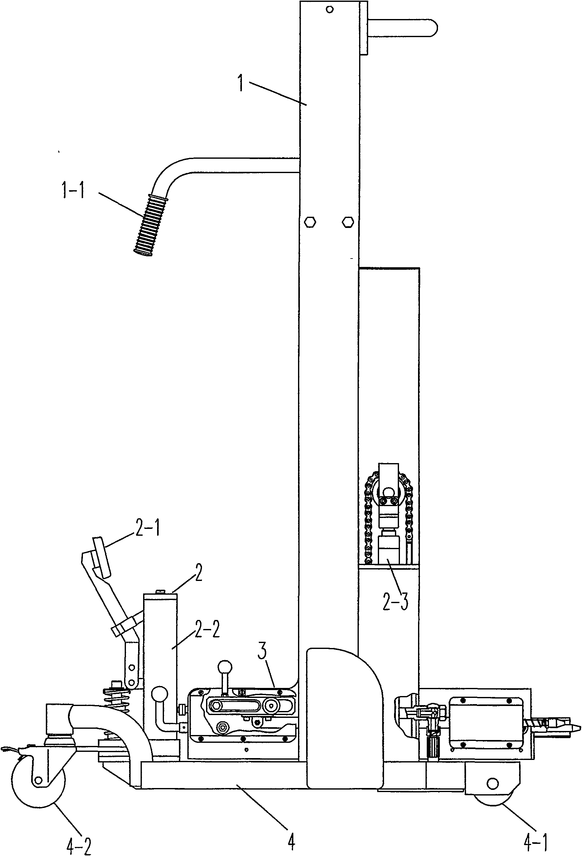
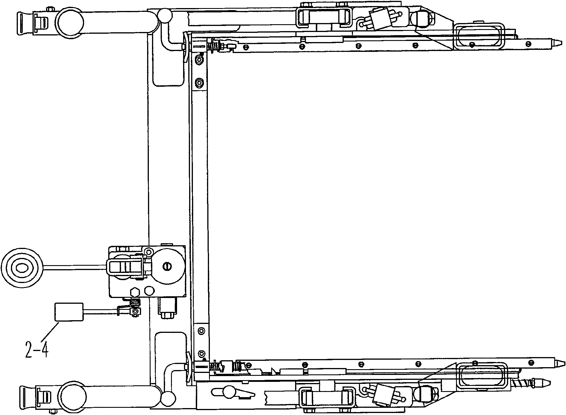
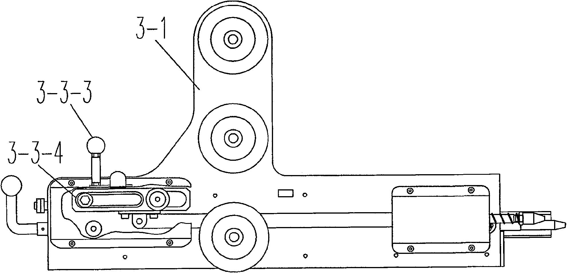
[0022] see Figure 1 to Figure 14 , the hydraulic service vehicle in the embodiment of the present invention includes a mast 1, a hydraulic system 2, a boom 3, and a vehicle frame 4. The mast 1 is matched with the boom 3 and is movably connected. 3. A boom frame 3-1, a connection unlocking device 3-2, and a positioning locking device 3-3 are provided. Connect unlocking device 3-2 to be provided with lower ball handle rod 3-2-1, enclosure plate 3-2-2, support plate 3-2-3, guide rail 3-2-4, pin 3-2-5, front Positioning seat 3-2-6, first spring 3-2-7, rear positioning seat 3-2-8, pull plate 3-2-9, connecting unlocking support 3-2-10, locking plate 3-2- 11. Second spring 3-2-12, connecting unlocking shaft 3-2-13, adjusting shaft 3-2-14, connecting pin shaft 3-2-15, lower ball handle rod 3-2-1 and front positioning seat 3-2-6, the rear positioning seat 3-2-8, the first spring 3-2-7 are matched and connected flexibly, the front positioning seat 3-2-6, and the rear positioning seat...
PUM
Abstract
The invention relates to a small transport vehicle, especially a hydraulic service vehicle specially used for loading, unloading and transporting power distribution circuit breakers, including a door frame, a hydraulic system, a boom, and a vehicle frame, and the door frame matches and moves with the boom Connection, the door frame is fixedly connected with the frame, the frame is equipped with two directional wheels and two universal wheels, the hydraulic system is equipped with a rising pedal, a fuel tank, a lifting cylinder, a descending pedal, the fuel tank is connected with the frame, and the lifting cylinder It is connected with the boom, and the boom is provided with a boom frame, a connecting unlocking device and a positioning locking device. The connecting unlocking device is installed on the two inner sides of the boom frame, and the positioning locking device is installed on the outside of the boom frame. The present invention has a reasonable structural design, and has the characteristics of being movable and lifting. The connection unlocking device ensures the connection locking between the present invention and the switch cabinet, and the positioning locking device ensures the locking between the present invention and the short circuit, and the connection unlocking device and the positioning locking device exist The interlocking relationship makes the short circuit breaker safe and reliable during loading and unloading and transportation, and the lifting is stable, the rotation is flexible, and the operation is convenient, which is conducive to reducing labor intensity, improving production efficiency, and realizing safe loading and unloading.
Description
Technical field: [0001] The invention is a hydraulic service vehicle specially used for loading, unloading and transporting distribution circuit breakers. Background technique: [0002] In the prior art, there is only a very simple trolley. Its structure is composed of 4 wheels and a platform. The short circuiter is transported to the trolley by manpower, and then the trolley is pushed for transportation. The trolley cannot be lifted, and there is no connection unlocking device and positioning The locking device is very inconvenient when loading and unloading the short circuiter, and it is very unsafe during loading, unloading and transportation. The short circuiter is easy to fall from the trolley, causing personal injury or damage to the short circuiter. Invention content: [0003] The technical problem to be solved by the present invention is to overcome the deficiencies in the prior art and provide a hydraulic service vehicle specially used for loading, unloading and t...
Claims
Application Information
Patent Timeline
Application Date:The date an application was filed.
Publication Date:The date a patent or application was officially published.
First Publication Date:The earliest publication date of a patent with the same application number.
Issue Date:Publication date of the patent grant document.
PCT Entry Date:The Entry date of PCT National Phase.
Estimated Expiry Date:The statutory expiry date of a patent right according to the Patent Law, and it is the longest term of protection that the patent right can achieve without the termination of the patent right due to other reasons(Term extension factor has been taken into account ).
Invalid Date:Actual expiry date is based on effective date or publication date of legal transaction data of invalid patent.