
Pixel structure

A technology of pixel structure and pixel area, used in optics, instruments, electrical components, etc.

Inactive Publication Date: 2009-11-04
CHUNGHWA PICTURE TUBES LTD
View PDF3 Cites 0 Cited by
  • Summary
  • Abstract
  • Description
  • Claims
  • Application Information

AI Technical Summary

Problems solved by technology

[0007] Another object of the present invention is to provide a pixel repair structure of a liquid crystal display, which uses the pixel repair design to solve the problem of bright or dark spots caused by the failure of the thin film transistor to operate normally, so that it has the ability to display grayscale of normal pixels

Method used


Image

  • Pixel structure
  • Pixel structure
  • Pixel structure

Examples


Embodiment Construction

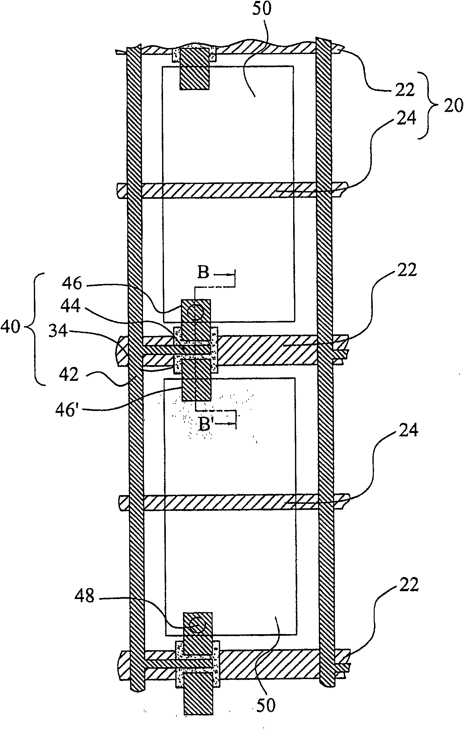
[0039] figure 2 It is a schematic plan view of the pixel structure of the present invention. Such as figure 2 As shown, in this embodiment, a plurality of scan lines 22 (scan lines) and a plurality of signal lines 42 are disposed on a substrate (not shown in the figure). The intersections of the scan lines 22 and the signal lines 42 define a plurality of pixel regions. A plurality of storage capacitor electrode lines 24 are arranged across the pixel area along the scanning line 22 and cross the signal line 42 . A plurality of pixel electrodes 50 (pixel electrodes) are respectively disposed in any pixel area. A plurality of thin film transistors 40 are respectively disposed on the scan lines 22 of each pixel area. Wherein, any thin film transistor 40 includes a gate electrode (gate electrode) (not shown on the figure); a source electrode 44 (source electrode); a first drain electrode 46 (drain electrode); and a second drain Electrode 46'. The gate electrode is electrica...


PUM


Abstract

A pixel structure of a liquid crystal display includes: a plurality of scanning lines and a plurality of signal lines defining a plurality of pixel areas; a plurality of storage capacitor electrode lines; a plurality of pixel electrodes; and a plurality of thin film transistors. Wherein, any thin film transistor is provided with a second drain electrode, wherein the second drain electrode is symmetrically arranged with the first drain electrode. The first drain electrode is arranged on one side of the gate electrode and is electrically connected to the pixel electrode, and the second drain electrode is symmetrically arranged on the other side of the gate electrode and connected to the pixel region. The pixel electrodes partially overlap and are electrically isolated from each other, wherein the repairing method of the present invention utilizes a laser bombardment process to fuse and short the second drain electrode and the pixel electrodes of adjacent pixel regions at the partially overlapped positions. The brightness displayed by the pixel of the present invention is completely the same as that of the upper pixel and is not a bright point, which can greatly reduce the repair time and improve the product yield.

Description

technical field [0001] The present invention relates to a liquid crystal display, and in particular provides a pixel structure suitable for a liquid crystal display. The present invention enables pixels that cannot operate normally to obtain normal display signals to repair defects. Background technique [0002] Thin Film Transistor-Liquid Crystal Display (TFT-LCD) is currently the most widely used flat panel display, which has the advantages of low power consumption, thin shape, light weight, and low voltage drive. Usually, the liquid crystal of a thin film transistor liquid crystal display is filled between a thin film transistor panel (panel) containing electrodes and a color filter (color filter, CF) panel containing electrodes, and the transparency of liquid crystals to light is provided by The voltage to each electrode is controlled. The image display area of ​​the TFT panel is composed of many pixels arranged in a matrix. [0003] In the production process of the pa...

Claims


Application Information

Patent Timeline
Patent Type & Authority Patents(China)
IPC IPC(8): H01L27/12H01L23/522H01L29/786H01L29/417G02F1/136
Inventor 林光祥游辉钟
Owner CHUNGHWA PICTURE TUBES LTD
Learn More