Manufacturing method of multichannel current sensor for new energy automobile

A current sensor, new energy vehicle technology, applied in the parts of electrical measuring instruments, only measuring current, measuring current/voltage, etc., can solve the problems of increasing connection materials, heavy overall weight, and virtual welding.

Active Publication Date: 2020-10-23
NINGBO CRRC TIMES TRANSDUCER TECH CO LTD
View PDF4 Cites 5 Cited by
  • Summary
  • Abstract
  • Description
  • Claims
  • Application Information

AI Technical Summary

Problems solved by technology

The current sensor with this structure mainly has the following problems: (1) The overall packaging of the product and the positioning of components are carried out in the way of glue filling, and the overall weight is heavy; (2) In order to meet the requirements of glue filling, an additional flow channel needs to be designed. This results in a larger product size; (3) The curing time of the potting glue is longer, prolonging the production cycle; (4) The debugging and other processes need to wait for the glue to be potted and cured. Process control and problem analysis; (5) Poor curing of potting glue can easily cause problems such as moisture absorption and stress, which will affect product accuracy and have certain risks
The current sensor with this structure mainly has the following problems: (1) The iron core is partially exposed after injection molding, which is prone to rust and rust, and the components have a short circuit risk under high temperature, humidity and vibration conditions; (2) The internal pins and the printed board The assembly method is welding, which is not easy to detect in mass production, and there are risks of missing soldering and false soldering; (3) The grounding method used in printed board assembly requires more materials for connection, which increases the cost

Method used


Image

  • Manufacturing method of multichannel current sensor for new energy automobile
  • Manufacturing method of multichannel current sensor for new energy automobile
  • Manufacturing method of multichannel current sensor for new energy automobile

Examples


Embodiment Construction

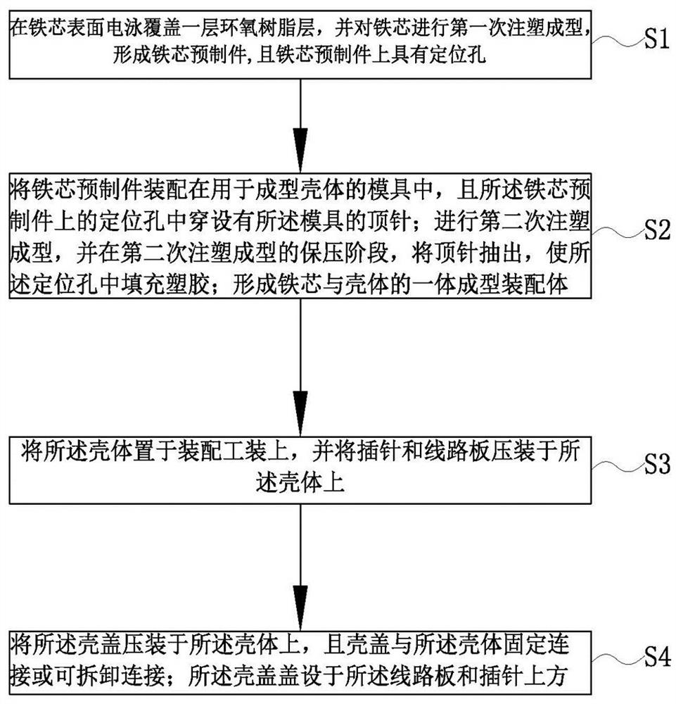
[0041] The following are specific embodiments of the present invention and in conjunction with the accompanying drawings, the technical solutions of the present invention are further described, but the present invention is not limited to these embodiments.

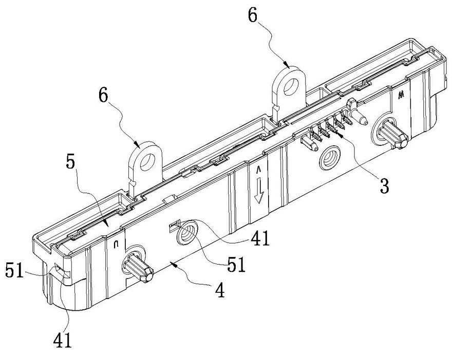
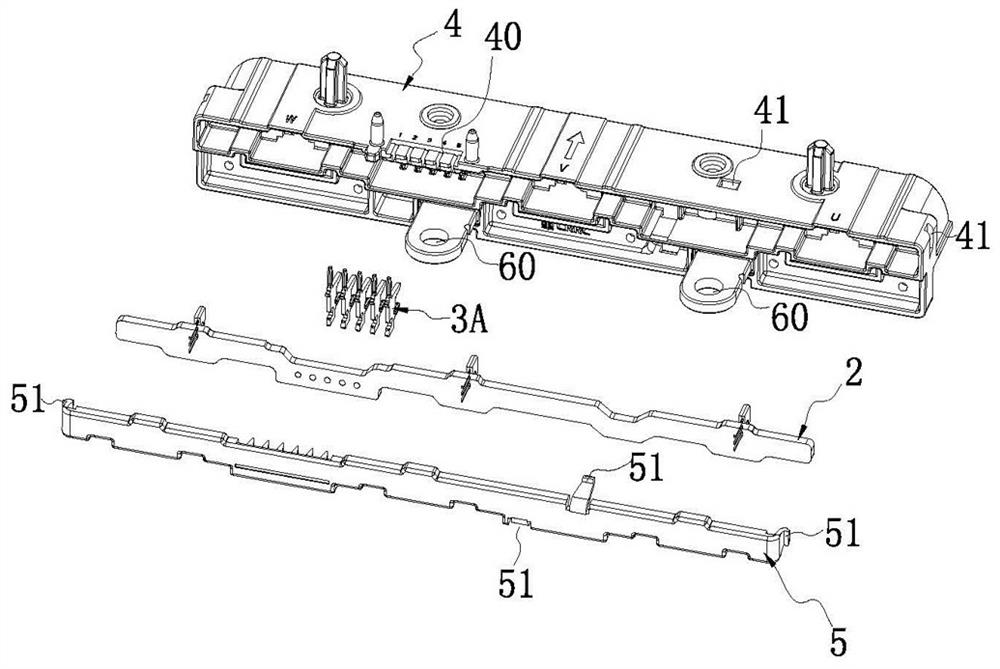
[0042] Such as Figure 2-4 As shown, a method for manufacturing a multi-channel current sensor for a new energy vehicle, wherein the multi-channel current sensor includes an iron core 1, a circuit board 2, pins 3, a housing 4, a housing cover 5 and mounting feet 6 The iron core 1 and the mounting feet 6 are integrally injection-molded with the housing 4, the pins 3 and the circuit board 2 are press-fitted on the housing 4, and the housing cover 5 is also press-fitted on the housing 4, and the cover is arranged on the plug-in The pin 3 and the top of the circuit board 2 ensure the stability of the overall structure of the product.

[0043] Such as figure 1 As shown, the manufacturing method of the multi-channel current sens...


PUM


Abstract

The invention relates to the technical field of automobile current sensors, and discloses a manufacturing method of a multichannel current sensor for a new energy automobile. The method comprises thesteps: S1, electrophoretically covering an epoxy resin layer on the surface of an iron core, and performing injection molding for the first time to form an iron core prefabricated member, wherein a positioning hole is formed in the iron core prefabricated member; S2, assembling the iron core prefabricated member in a mold for forming a shell, wherein a centre of the mold penetrates through the positioning hole in the iron core prefabricated member; carrying out secondary injection molding, extracting the centre at a pressure maintaining stage of the secondary injection molding, and filling plastic in the positioning hole; and forming an integrally formed assembly body of the iron core and the shell; S3, pressing a contact pin and a circuit board on the shell; and S4, pressing a shell coveron the shell, wherein the shell cover is arranged above the circuit board and the contact pin. The manufacturing method of the multichannel current sensor for the new energy automobile has the advantages that the reliability of the current sensor in a high-temperature wet environment is improved, the shock resistance and impact fatigue resistance are high, welding is not needed, and the process is simple.

Description

technical field [0001] The invention relates to the technical field of automotive current sensors, in particular to a method for manufacturing a multi-channel current sensor for new energy vehicles. Background technique [0002] As the country vigorously advocates energy saving and environmental protection, new energy vehicles have gradually moved from a new technological product to the lives of ordinary people. The management of batteries and motor drive control in new energy vehicles are inseparable from the application of current sensors. Current sensors can measure, detect and control measurement parameters such as current, voltage, and temperature. There are mainly two types of existing multiple current sensors (such as triple sensors). [0003] A structure of a current sensor, such as the integrated current sensor disclosed in "CN207007919U" for phase current detection of an automobile electronic control system. In this structure, the current sensor is composed of a ...

Claims


Application Information

Patent Timeline
Patent Type & Authority Applications(China)
IPC IPC(8): B29C45/00B29C45/14B29C45/40B29C45/44G01R19/00G01R1/04B29L31/34
CPCB29C45/0053B29C45/14B29C45/1418B29C45/401B29C45/44B29C2045/14245B29C2045/1486B29L2031/34G01R1/0408G01R19/0092
Inventor 马华超胡冬青胡玄叶柳凯朱文琴张文江吴如兆
Owner NINGBO CRRC TIMES TRANSDUCER TECH CO LTD
Why Eureka
Try Eureka