Control circuit for power converter

A power converter and control circuit technology, applied in output power conversion devices, conversion of DC power input to DC power output, control/regulation systems, etc., can solve problems such as low-pass filtering characteristics and waveform distortion

Active Publication Date: 2009-11-04
SYST GEN
View PDF4 Cites 0 Cited by
  • Summary
  • Abstract
  • Description
  • Claims
  • Application Information

AI Technical Summary

Problems solved by technology

[0008] above the feedback voltage V F , which is sent to the voltage detection terminal DET of the controller 25 through a resistor 22, so the controller 25 will generate a detection voltage V DET , and for the voltage detection terminal DET of the controller 25 to detect the feedback voltage V F , but because a parasitic capacitance 23 is coupled to the resistor 22, it will cause a low-pass filter characteristic, resulting in the feedback voltage V F will be filtered
In addition, the power converter will shorten the control signal V G The turn-on time T ON , according to equation (1), it will also shorten the feedback voltage V F The discharge time T DS , which will cause the detection voltage V DET As shown in the second figure, the waveform distortion occurs, so the controller 25 will detect the low-voltage feedback voltage V F

Method used


Image

  • Control circuit for power converter
  • Control circuit for power converter
  • Control circuit for power converter

Examples


Embodiment Construction

[0062] In order to enable the examiner to have a better understanding and understanding of the structural features and achieved effects of the present invention, I would like to provide a diagram of a better embodiment and a detailed description, as follows:

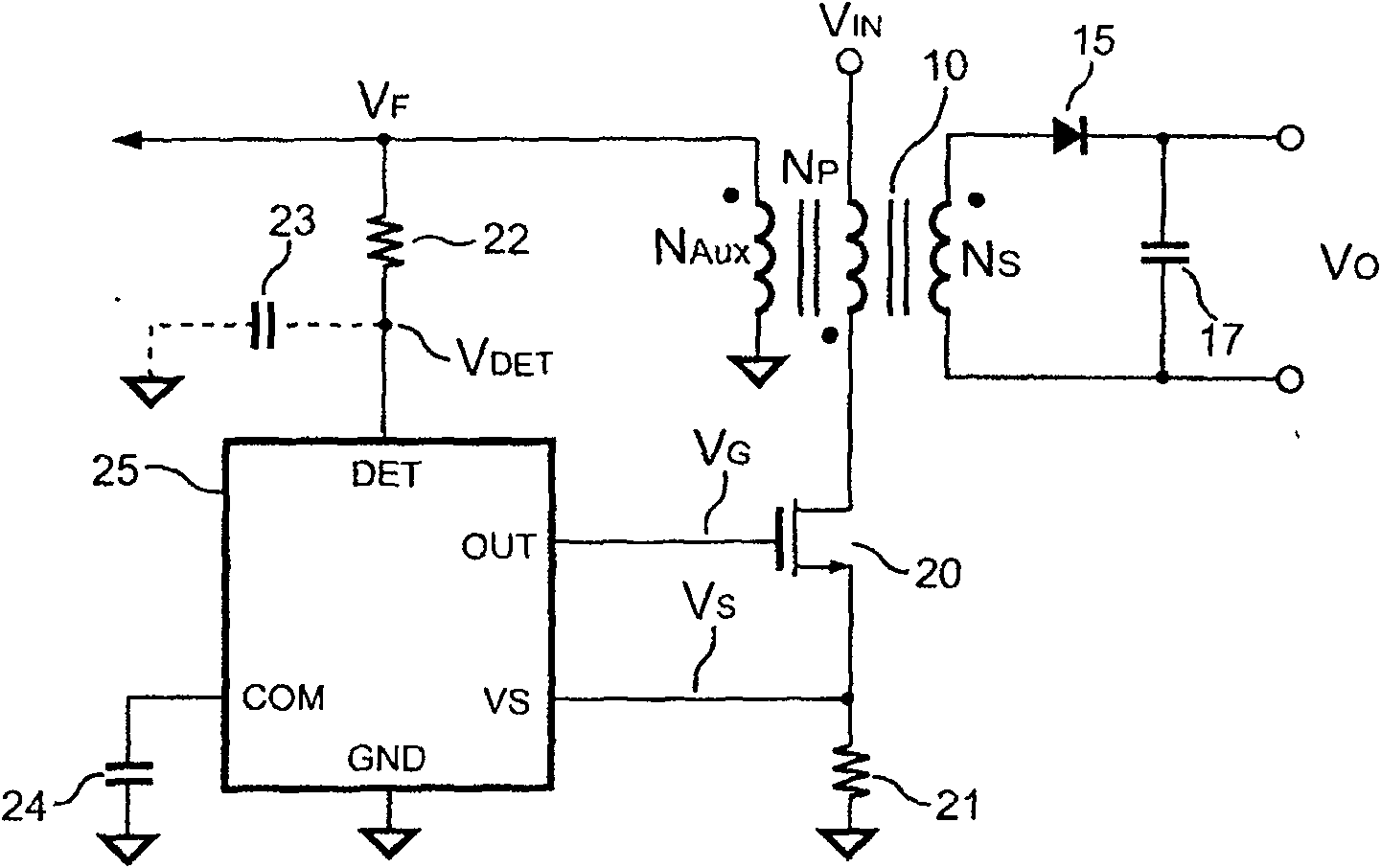
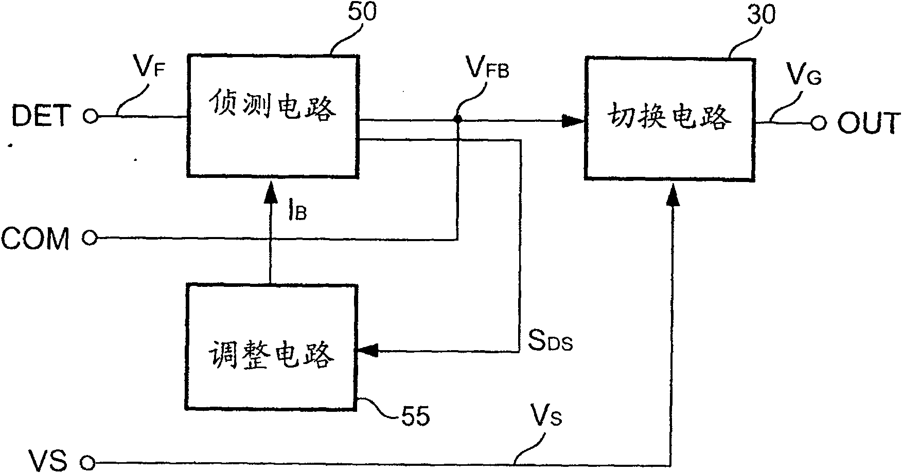
[0063] The control circuit of the power converter of the present invention includes a switch and a controller. The controller generates a control signal to control the coupled switch to switch the transformer of the power converter. see image 3 , is a block diagram of a controller of a preferred embodiment of the present invention. As shown in the figure, the controller of the present invention includes a switch circuit 30 , a detection circuit 50 and an adjustment circuit 55 . The detection circuit 50 is coupled to the transformer 10 via the voltage detection terminal DET to detect the feedback voltage V of the transformer 10 F , to depend on the feedback voltage V F generate a first signal V FB and a second signal...


PUM


Abstract

The invention relates to a control circuit of a power converter, which is used to detect a feedback voltage of a transformer of the power converter. The control circuit includes a switch, a detection circuit and a switching circuit, and the switch is coupled to the transformer for switching Transformer, the detection circuit is coupled to the transformer for detecting the feedback voltage, so as to generate a first signal according to the feedback voltage, and the switching circuit generates a control signal according to the first signal, so as to control the switch and adjust the output of the power converter, due to the power conversion When the device is under light load, the pulse width of the feedback voltage will be shortened, so the detection circuit generates a bias signal to help the detection of the feedback voltage. The bias signal is inversely proportional to the discharge time of the transformer, that is, the bias signal when the discharge time decreases In addition, the switching circuit generates a blanking signal according to the control signal to ensure the minimum pulse width of the feedback voltage.

Description

Technical field: [0001] The invention relates to a power converter, in particular to a control circuit of the power converter. Background technique: [0002] According to, power converters are widely used to provide regulated output power today. In consideration of safety, the primary side and the secondary side of the power converter must be isolated, so the power converter is usually provided with a transformer for providing isolation and transferring energy. see figure 1 , is the circuit diagram of a conventional power converter. As shown in the figure, a conventional power converter is provided with a transformer 10, which includes a primary winding N P , primary and secondary side winding N S with an auxiliary winding N AUX , primary side winding N P respectively coupled to an input voltage V IN with a switch 20 . When the switch 20 is turned on, the primary side of the transformer 10 will store energy. Once the switch 20 is turned off, the transformer 10 will r...

Claims


Application Information

Patent Timeline
Patent Type & Authority Patents(China)
IPC IPC(8): H02M3/28H02M3/335
Inventor 杨大勇
Owner SYST GEN
Why Eureka
Try Eureka