Current transformer

A technology of current transformer and shunt, applied in the direction of inductor, voltage/current isolation, transformer/inductor coil/winding/connection, etc., can solve problems such as Rogowski coil interference, achieve less magnetic field interference, eliminate secondary drag. tail phenomenon, the effect of simple structure

Inactive Publication Date: 2013-03-27
NANJING JIANGBEI AUTOMATION TECH
View PDF9 Cites 5 Cited by
  • Summary
  • Abstract
  • Description
  • Claims
  • Application Information

AI Technical Summary

Problems solved by technology

However, the external magnetic field has great interference on the Rogowski coil

Method used


Image

  • Current transformer
  • Current transformer

Examples


Embodiment Construction

[0021] Further illustrate the present invention below in conjunction with accompanying drawing.

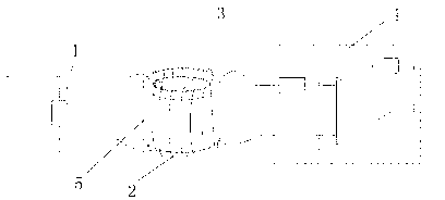
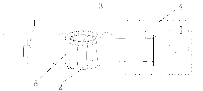
[0022] see figure 1 , the current transformer provided by the present invention includes a magnetic ring 5, a primary winding 2, a secondary winding 3, a shunt 1 connected in series on the primary cable, the primary winding 2 and the secondary winding 3 are wound on the magnetic ring 5, The primary winding 2 is connected in parallel with the shunt 1; when the voltage at the output end of the secondary winding 3 is less than 100 millivolts, the output end of the secondary winding 3 is connected to the input end of the operational amplifier 4; the shunt adopts a high-precision small resistance The resistance.

[0023] Among them, the cross-sectional area of ​​the magnetic ring is 0.2 c㎡-100 c㎡. The number of turns of the primary winding is 5 turns-3000 turns, preferably 10 turns-2000 turns. The number of turns of the secondary winding is 5 turns-50000 turns, preferably 10 turns-2...


PUM

PropertyMeasurementUnit
areaaaaaaaaaaa
electrical resistanceaaaaaaaaaa

Abstract

The invention relates to a current transformer, which comprises a magnetic ring, a primary winding, a secondary winding and a shunt; wherein the shunt is connected with a circuit to be tested in series, the primary winding and the secondary winding are wound on the magnetic ring, the primary winding is connected with the shunt in parallel, and output signals of the secondary winding are used for measurement and analysis. The current transformer has a simple structure and cannot be easily interfered by an external magnetic field. True reflection of the attenuation state of the maximum aperiodic component, and elimination of secondary smearing after cutoff of faults can be realized according to optimal selection of parameters. The current transformer can be applied in waveform following and combining units after fault recording and reclosing multiple times, as well as traditional relay protection and primary current transformers.

Description

technical field [0001] The invention designs a current transformer, especially relates to a current transformer with good transition process response for measuring short-circuit current and non-periodic components in power system microcomputer relay protection, and can be used in fault recording, multiple Waveform following after reclosing, merging unit, traditional protection and primary current transformer. Background technique [0002] When the primary equipment of the power system fails, a current more than 20 times the normal working current will appear in the system. In addition, due to the inductance in the circuit, the short-circuit current will not increase suddenly. Therefore, at the beginning of the moment (t=0), there will also be a direct current that is opposite to the periodic component current and decays, that is, the non-periodic component, which is superimposed on the short-circuit current. When the initial voltage angle is 0° or 180°, the maximum instant...

Claims


Application Information

Patent Timeline
Patent Type & Authority Applications(China)
IPC IPC(8): H01F38/32H01F27/28G01R15/18
Inventor 赵晶晶
Owner NANJING JIANGBEI AUTOMATION TECH
Why Eureka
Try Eureka