Method and device for imaging optimized angle of well earthquake reflected wave

An inter-well seismic and reflected wave technology, which is applied in the seismology and seismic signal processing for logging records, can solve the problem of reduced imaging resolution, low imaging resolution, and inability to truly reflect the vertical and horizontal changes of the underground medium, etc. problem, to avoid waveform distortion and improve the resolution of reflection imaging

Inactive Publication Date: 2010-01-13
中国石化集团胜利石油管理局有限公司
View PDF0 Cites 6 Cited by
  • Summary
  • Abstract
  • Description
  • Claims
  • Application Information

AI Technical Summary

Problems solved by technology

[0004] The technical problem to be solved by the embodiments of the present invention is to provide a cross-well seismic reflection wave optimal angle imaging method to solve the problem that the imaging resolution is reduced due to the wide-angle reflection of the reflection wave and cannot truly reflect the vertical and horizontal changes of the underground medium.
[0005] Another technical problem to be solved by the embodiments of the present invention is to provide a preferred angle imaging device for interwell seismic reflection waves to solve the problems of low imaging resolution and inability to truly reflect the vertical and horizontal changes of underground media in existing reflection wave imaging devices

Method used


Image

  • Method and device for imaging optimized angle of well earthquake reflected wave
  • Method and device for imaging optimized angle of well earthquake reflected wave
  • Method and device for imaging optimized angle of well earthquake reflected wave

Examples


Embodiment Construction

[0034] In order to make the purpose and technical solution of the present invention clearer, the present invention will be described in detail below in conjunction with the accompanying drawings.

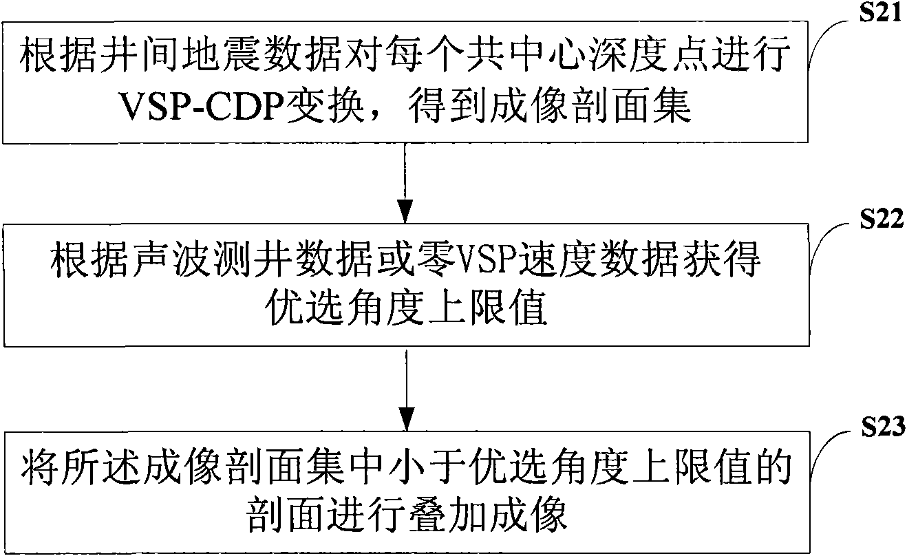
[0035] figure 2 It is a flow chart of a preferred angle imaging method for interwell seismic reflection waves provided by an embodiment of the present invention. Such as figure 2 As shown, the method includes the following steps:

[0036] S21. Perform VSP-CDP transformation on each common center depth point according to the interwell seismic data in the target area to obtain an imaging section set;

[0037] S22. Obtain the upper limit value of the optimal angle according to the acoustic logging data or zero VSP velocity data in the target area;

[0038] S23. Collect the imaging sections that are smaller than the upper limit of the preferred angle and perform superimposed imaging.

[0039] In the embodiment of the present invention, the lower limit value of the preferred angle ...


PUM


Abstract

The invention discloses a method for imaging an optimized angle of a well earthquake reflected wave, comprising the following steps: carrying out VSP-CDP conversion of each concentrical depth point according to well data of an objective area to obtain an imaging section set; obtaining an optimized angle upper limit value according to acoustic logging data or zero VSP speed data of the objective area; and stacking and imaging sections which are smaller than the optimized angle upper limit value in the imaging section set. The method can eliminate wave shape distortion, frequency reduction, polarity inversion and statistical noise interference of a small-angle area for wide-angle reflection and can increase a reflected wave imaging resolution ratio to really reflect the vertical and horizontal variation of underground media.

Description

technical field [0001] The invention belongs to the field of seismic data processing, and in particular relates to a preferred angle imaging method and device for interwell seismic reflection waves. Background technique [0002] At present, the cross-well seismic reflection wave imaging method is: stacking on the common center depth point gather or the common shot point gather, and each common center depth point gather can generate a vertical seismic section-common depth point (Vertical Seismic Profiling-Common Depth Point (VSP-CDP for short) imaging, multiple common center depth point gathers generate multiple VSP-CDP imaging profile sets, and then perform full-angle stacking imaging on all profiles in the profile set. Such as figure 1 As shown in , a schematic diagram of the effect of full-angle superimposed imaging of reflected waves in the Ken 71 area of ​​Shengli Oilfield is given. [0003] In the process of realizing the present invention, the inventor found that the...

Claims


Application Information

Patent Timeline
Patent Type & Authority Applications(China)
IPC IPC(8): G01V1/28G01V1/40
Inventor 王延光左建军魏国华魏洪泉孙卫国
Owner 中国石化集团胜利石油管理局有限公司
Why Eureka
Try Eureka