
Design construction method of rectangular infiltration gallery for stabling water volume

A rectangular, seepage canal technology, applied in the seepage canal field, can solve the problems of cut-off and poor water flow in seepage canals, and achieve the effects of fast flow rate, good water intake effect and stable water volume.

Inactive Publication Date: 2009-12-02
浙江净水楼建设投资有限公司
View PDF4 Cites 5 Cited by
  • Summary
  • Abstract
  • Description
  • Claims
  • Application Information

AI Technical Summary

Problems solved by technology

Gradually make the sand and pebbles flowing into the seepage channel form silt at the bottom of the channel3, resulting in poor water flow in the seepage channel, or even stop flow in severe cases

Method used


Image

  • Design construction method of rectangular infiltration gallery for stabling water volume
  • Design construction method of rectangular infiltration gallery for stabling water volume
  • Design construction method of rectangular infiltration gallery for stabling water volume

Examples


specific Embodiment approach 1

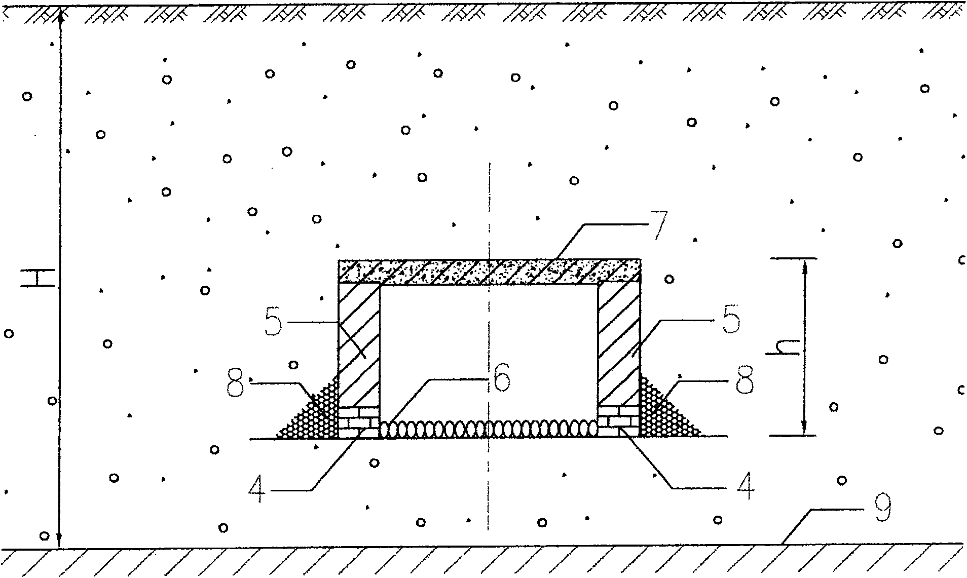
[0035] Such as image 3 The method for designing and constructing a rectangular seepage trench without digging into the aquifer bottom plate in the aquifer includes the following steps:

[0036] (1) Excavation: excavate the soil layer or sand and pebble layer to the design depth (elevation), but do not dig into the aquifer floor 9 in the aquifer;

[0037] (2) Dry masonry: Strip bricks, cement prefabricated blocks or strip stones are dry masonry arranged on the lower part of the two side walls of the rectangular seepage trench, with at least one horizontal joint and at least one vertical joint intersecting to meet the design requirements The water inlet slit array 4 of height, the slit of described water inlet slit array is maximum 3mm, and it is characterized in that horizontal slit and vertical slit only enter water and do not enter sand pebble. Therefore, the water output will not be reduced;

[0038] (3) Mortar masonry: the upper part of the dry masonry inlet joint array ...

specific Embodiment approach 2

[0042] Such as Figure 4 The method for designing and constructing the rectangular seepage channel of the aquitard floor dug into the aquifer shown in the aquifer includes the following steps:

[0043] (1) Excavation: the design depth (elevation) of excavating the soil layer or gravel and pebble layer should be dug to the aquifer floor 9 in the aquifer;

[0044] (2) Dry masonry: Strip bricks, cement prefabricated blocks or strip stones are dry masonry arranged on the lower part of the two side walls of the rectangular seepage trench, with at least one horizontal joint and at least one vertical joint intersecting to meet the design requirements The water inlet slit array 4 of height, the slit of described water inlet slit array is maximum 3mm, and it is characterized in that horizontal slit and vertical slit only enter water and do not enter sand pebble. Therefore, the water output will not be reduced;

[0045] (3) Mortar masonry: the upper part of the dry masonry inlet joint...


PUM


Abstract

A method for designing and constructing a rectangular seepage channel with stable water volume, comprising the following steps: digging, dry laying, mortar laying, stone discharge, capping, backfilling a graded pebble filter layer and backfilling a mixed sand and pebble filter layer. Dry masonry is to have water inlet joint arrays at the bottom of the two side walls of the rectangular seepage trench. Mortar masonry is to use at least one of block stones, cement blocks, bricks, concrete prefabricated blocks or concrete tamping to build the two side walls of the rectangular seepage trench to the design total height. The height of the stone-discharging foundation and the bottom height of the two side walls of the dry-laid rectangular seepage trench as well as the size of pebbles, bricks and block stones shall be determined according to the design requirements. It has the advantages of digging and masonry, relatively less affected by landslides, good water inflow effect and stable water volume. The design and construction method of the rectangular seepage canal of the present invention effectively solves the drawbacks of the existing circular seepage canal's water inlet holes being blocked after advanced sand and the water inflow plummets, greatly improves the water production of the water collection and water intake structures, and makes each large mouth The water between the well and the infiltration canal can flow into the water collection structure continuously.

Description

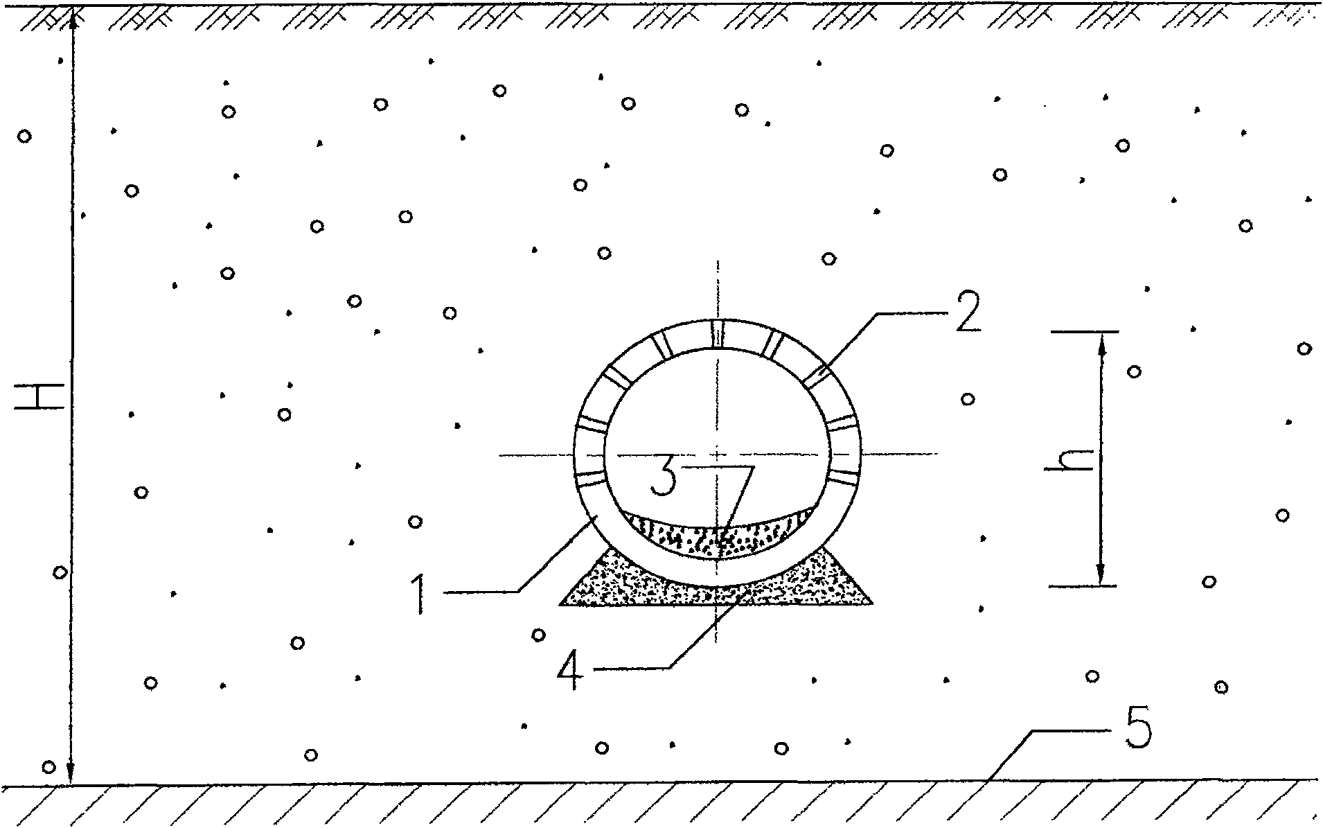
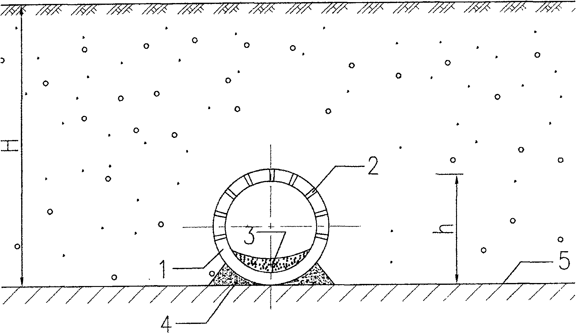
technical field [0001] The invention relates to a seepage canal, in particular to a design and construction method for a rectangular seepage canal with stable water volume. Background technique [0002] The design and construction method of seepage canal in the prior art is as follows: figure 1 Circular seepage channels for the aquitard floor not dug deep into the aquifer and as shown figure 2 Two types of circular infiltration trenches are shown with the aquitard floor dug deep into the aquifer. The two design and construction methods of infiltration trenches include the following steps: [0003] (1) Excavation: first dig the soil layer or gravel layer to the design depth (elevation); [0004] (2) Backup pipe: round cement pipe, steel pipe or plastic pipe 1: [0005] (3) Digging holes: Dig water inlet holes and eyes 2 of different sizes on the surface of the pipe wall of the circular cement pipe, steel pipe or plastic pipe 1; . The upper part of the steel pipe or plas...

Claims


Application Information

Patent Timeline
Patent Type & Authority Patents(China)
IPC IPC(8): E02D29/045E02B11/00
Inventor 陈先土
Owner 浙江净水楼建设投资有限公司
Learn More