Chain guide structure of mining machine

A guiding structure and chain technology, applied in the direction of slitting machinery, conveyors, propulsion, etc., can solve the problems of guide card wear and other problems

Inactive Publication Date: 2009-12-02
CATERPILLER GLOBAL MINING EURO GMBH
View PDF7 Cites 0 Cited by
  • Summary
  • Abstract
  • Description
  • Claims
  • Application Information

AI Technical Summary

Problems solved by technology

The known construction has proven to be basically reliable, but problems arise after the plow has been in operation for a while, since the guide clips are subject to considerable wear due to the permanent contact with the non-load-bearing branch of the chain and can only be removed with great effort Remove and replace with new guide card

Method used


Image

  • Chain guide structure of mining machine
  • Chain guide structure of mining machine
  • Chain guide structure of mining machine

Examples


Embodiment Construction

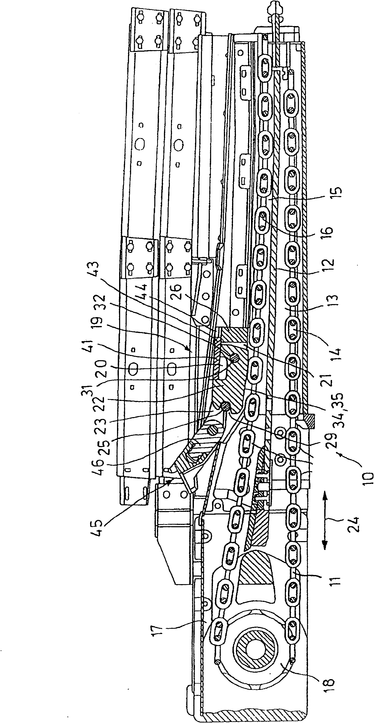
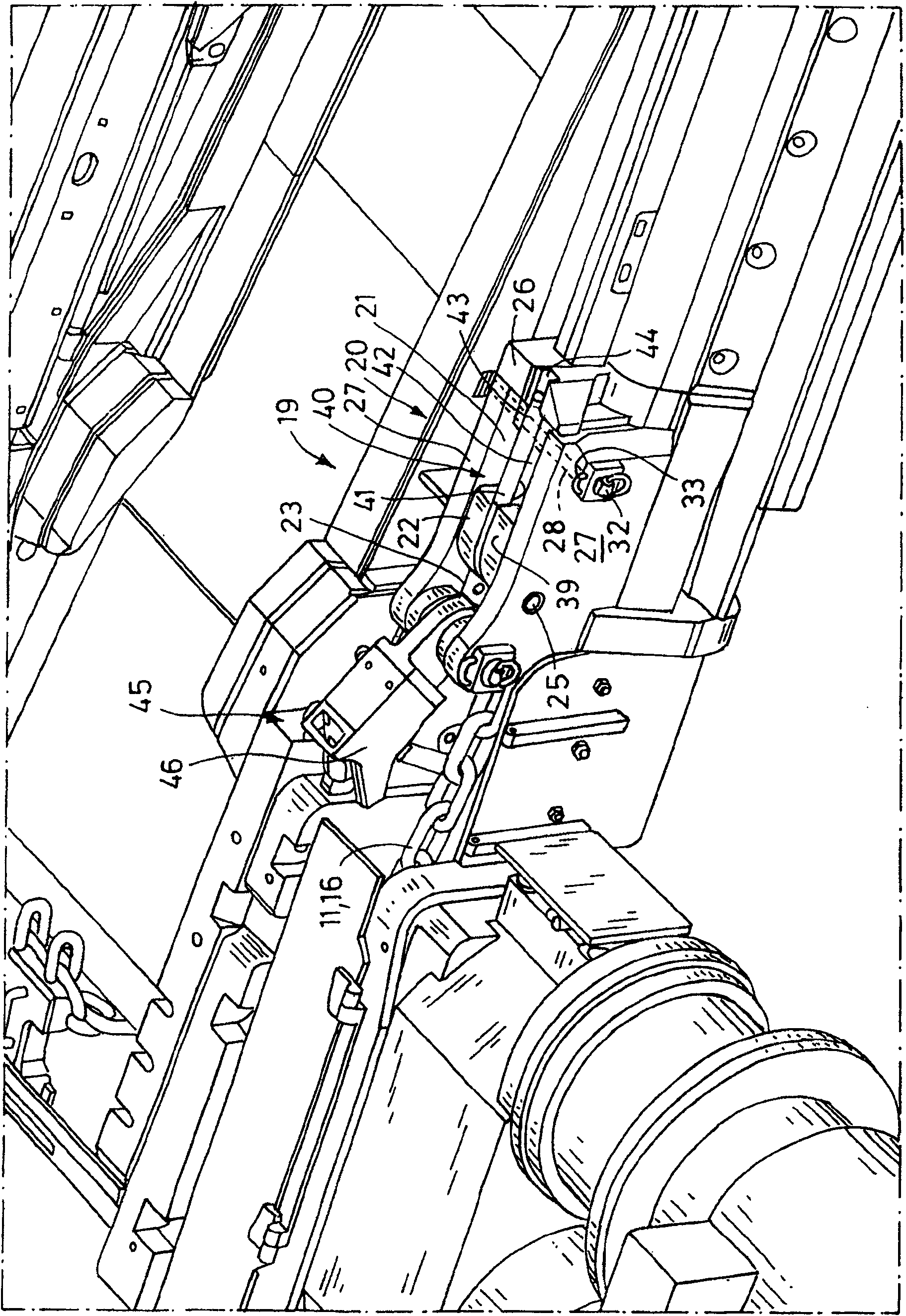
[0017] A chain guide, indicated generally at 10 in the drawing, is used to guide a drive chain 11 of a coal plow used in underground mining for extracting coal.

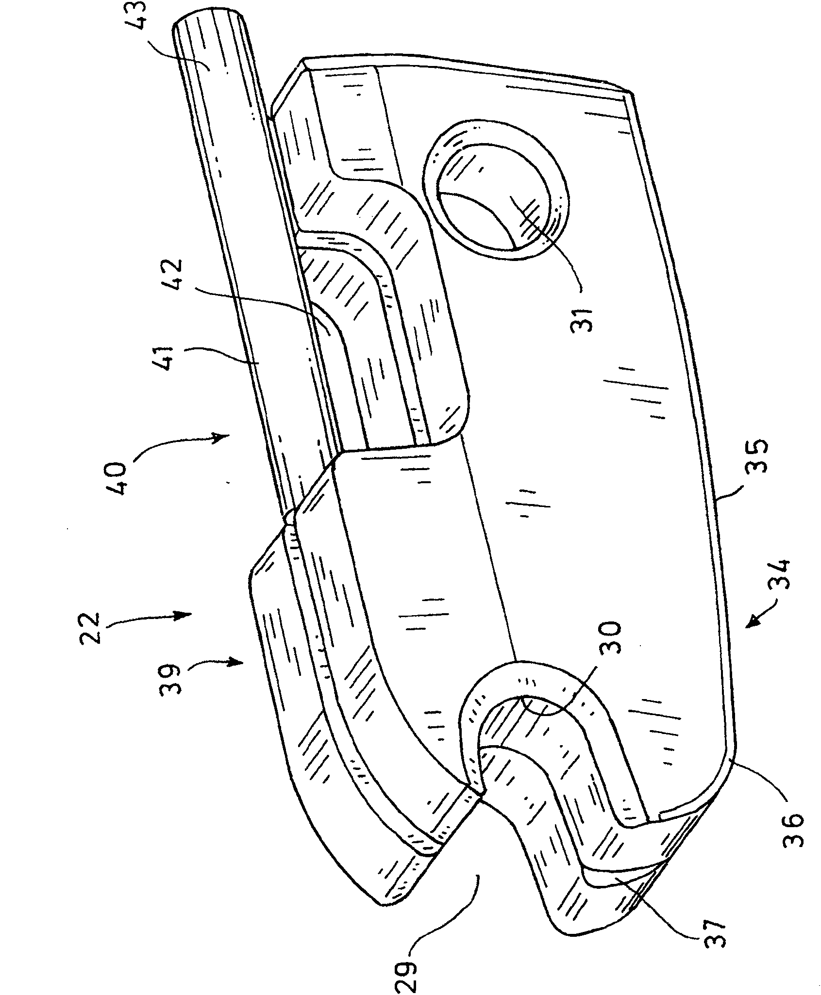
[0018] The chain guide 10 has in the plow chain guide 12 a first chain groove 13 for the load-bearing leg 14 of the drive chain and a second chain groove 15 which supports the non-load-bearing leg 16 of the drive chain. Attached to the end regions of the chain grooves 13, 15 is a transmission station 17 with a drive sprocket 18, which is wound by the drive chain 11 and is used to pull the chain through the chain grooves, as is known. In the transition area 19 between the second chain groove 15 and the transmission station 17, establish a chain guide 20 for the non-bearing branch 16 of the transmission chain 11. This chain guide mainly consists of an upper and lower opening mounting seat 21 and It consists of a pressure plate 22 fitted inside it and locked in its installed position. Mounting seat 21 passes through a ...


PUM


Abstract

The invention relates to a chain guide structure on a mining machine, in particular to a plow chain guide structure on a coal plow, which has a first chain slot for the load-bearing branch of the transmission chain of the mining machine and a first chain slot for the non-load-bearing branch The second chain groove of the drive chain is provided with at least one transmission station and / or a deflection station with a drive sprocket or a deflection sprocket for the transmission chain in the area of ​​the end of the drive chain, wherein at least one of the chain grooves leads to A chain guide device for the load-bearing branch and / or non-load-bearing branch of the transmission chain is provided in the transition area of ​​the transmission station and / or the steering station, and it is characterized in that: the chain guide device (20) has a drive chain (11) Open mounting seat (21) defined at one end face (23) by a hinge pin (25) arranged perpendicular to the chain movement direction (24) and a pressure plate (22) at least on one end face side thereof The end of the hinge pin (25) is equipped with a pin seat (29) with one side opening matching the hinge pin (25) and a locking device, and the pressure plate has a pressure plate installed in the mounting seat (21) on its bottom surface (34). And be attached to the pressing surface (35) on the drive chain (11) under the locked state.

Description

technical field [0001] The invention relates to a chain guide structure on mining machinery, in particular to a coal plow chain guide structure for coal plows. Background technique [0002] Known from DE 1811009A is a transmission station for chain-type scraper conveyors or coal plows, wherein for the drive chain, the guide in the transition zone to the chute section of the conveyor or the plow to the device, The chain is guided by means of an approximately wedge-shaped drive frame with a substantially flat first guide rail and an inclined second guide rail arranged at an acute angle to it, the non-load-bearing and load-bearing branches of the drive chain It abuts directly on the guide rail before and after it turns around the star sprocket of the transmission station. [0003] A chain guide of this type is known from DE 20106732 U, in which the chain guide is essentially formed by a guide clip which is fixedly arranged in the entry and exit regions of the second chain groo...

Claims


Application Information

Patent Timeline
Patent Type & Authority Patents(China)
IPC IPC(8): E21C27/34B65G19/28E21C29/10
CPCE21C29/10E21C27/34
Inventor 赖纳·埃克尔曼乌韦·蒂勒森诺伯特·黑塞格哈德·西彭科尔特克劳斯·杜恩克亚当·克拉比施
Owner CATERPILLER GLOBAL MINING EURO GMBH
Why Eureka
Try Eureka